Industrial dust collector

A technology for industrial vacuum cleaners and dust buckets, applied in vacuum cleaners, suction filters, manufacturing tools, etc., can solve the problems of restricting air flow, the vacuum cleaner cannot work normally and continuously, and the dust and humidity are high, so as to achieve the effect of improving work efficiency.

Pending Publication Date: 2021-03-30
POSITEC POWER TOOLS (SUZHOU) CO LTD
View PDF0 Cites 2 Cited by
  • Summary
  • Abstract
  • Description
  • Claims
  • Application Information

AI Technical Summary

Problems solved by technology

Because there is a lot of dust in the workplace, and the dust similar to concrete has high humidity and heavy weight, it is easy to block the filter, thereby restricting the air flow and making the vacuum cleaner unable to work normally.
The surface of the filter must therefore be cleaned manually frequently or replaced with a new filter

Method used


Image

  • Industrial dust collector
  • Industrial dust collector
  • Industrial dust collector

Examples


specific Embodiment approach 1

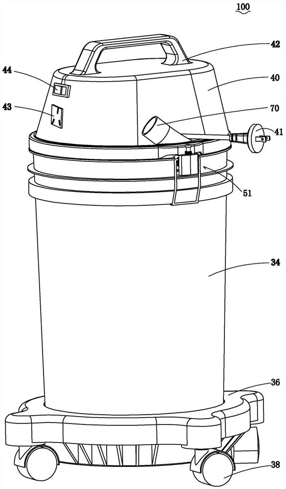
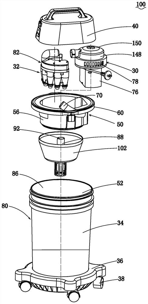
[0056] See figure 1 and figure 2 , the industrial vacuum cleaner 100 includes an airflow generating device 30, a separation device 32 communicating with the airflow generating device 30, and a dust bucket 34 for collecting dust. The lower part of the dust bucket 34 can be installed on the base 36, and a plurality of rollers 38 are arranged below the base 36, so that the vacuum cleaner 100 can be easily moved as required. A protective cover 40 can be provided on the top of the dust bucket 34, and the protective cover 40 can cover the airflow generating device 30 for protecting the airflow generating device 30, and can also be provided with a handle 42 to facilitate the movement of the vacuum cleaner 100. The industrial vacuum cleaner 100 of the present application is only a customary name, and is not limited to its use occasions. The industrial vacuum cleaner 100 can be widely used in various occasions such as rooms and workshops for cleaning work.

[0057] The main switch 4...

specific Embodiment approach 2

[0122] Such as Figure 12 to Figure 13 As shown, the second embodiment of the present invention discloses an industrial vacuum cleaner 200, including an airflow generating device 230, a separating device 232 communicated with the airflow generating device 230, and a dust bucket 234 for collecting dust. The lower part of the dust bucket 234 can be installed on the base 236, and a plurality of rollers 238 are arranged below the base 236, so that the vacuum cleaner 200 can be easily moved as required. A protective cover 240 can be provided on the top of the dust bucket 234 , and the protective cover 240 can cover the airflow generating device 230 to protect the airflow generating device 230 , and can also be provided with a handle 242 to facilitate the movement of the vacuum cleaner 200 .

[0123] The separation device 232 includes a multi-stage separation device including a primary separation device 280 , a secondary separation device 282 and a tertiary separation device 244 . ...


PUM


Abstract

The invention provides an industrial dust collector. The industrial dust collector comprises a dust collection guide pipe, an airflow generation device which is used for sucking air from the dust collection guide pipe to generate airflow and comprises a motor and a fan driven by the motor; a first-stage separation device which comprises a dust barrel, wherein the dust barrel comprises a side walland an accommodating cavity formed by the side wall, and the accommodating cavity is communicated with the dust collection guide pipe; a connecting channel which comprises an inlet and an outlet, wherein the inlet is communicated with the containing cavity; and a second-stage separation device which is communicated with the outlet and the airflow generation device. According to the industrial dustcollector, the connecting channel is arranged between the first-stage separation device and the second-stage separation device, so that blockage between the first-stage separation device and the second-stage separation device is avoided, the industrial dust collector can continuously collect dust with large suction force, and the working efficiency is improved.

Description

technical field [0001] The invention relates to an industrial vacuum cleaner. Background technique [0002] Industrial vacuum cleaners are usually used to collect large areas of dust-generating sites; or directly connected to the ash outlet of dust-producing tools, such as grinders, sanders, slotting machines, etc.; or to process metal, plastic, or other concrete or stone, etc. Material. In these vacuum cleaners, dust collection buckets, motors and fans for generating air flow, cloth-based bag separation filter devices, power switches, power cords with plugs, and the like are generally included. The motor and fan create a vacuum, and the dust-laden air enters the dust collection bucket through the suction pipe and flows to the bag-type separation filter device, where most of the dust can be separated from the air flow and fall into the dust collection bucket; Follow the airflow into the post-stage cylindrical paper-based filter (Happa), but some will be filtered again by t...

Claims


Application Information

Patent Timeline
Patent Type & Authority Applications(China)
IPC IPC(8): A47L7/00A47L9/00A47L9/10
CPCA47L7/00A47L9/00A47L9/10A47L9/16B08B5/04B24B55/06B04C5/26
Inventor 张士松毋宏兵钟红风
Owner POSITEC POWER TOOLS (SUZHOU) CO LTD
Why Eureka
Try Eureka