Multi-angle metal bending device and method for automobile part machining

An auto parts and bending device technology, which is applied in the field of multi-angle metal bending devices for auto parts processing, can solve the problems of difficulty in achieving fully automatic mechanical operation, reducing the processing efficiency of metal parts, and low bending metal work efficiency, etc. To achieve the effect of improving applicability and practicability, improving bending efficiency, and improving bending effect

Inactive Publication Date: 2021-03-30
宁波曼汶智能装备有限公司
View PDF0 Cites 0 Cited by
  • Summary
  • Abstract
  • Description
  • Claims
  • Application Information

AI Technical Summary

Problems solved by technology

[0003] In the process of bending metal, the existing metal bending device often needs manual auxiliary operation, and it is difficult to achieve fully automatic mechanical operation, resulting in low work efficiency when bending metal, and causing the staff to have certain difficulties. potential safety hazard; at the same time, the existing metal bending device does not have the metal cooling function, after the metal is bent, the temperature of the bending part will be high, if the temperature of the bending part is not cooled, the staff may be scalded, thereby reducing the Overall machining efficiency of metal parts

Method used


Image

  • Multi-angle metal bending device and method for automobile part machining
  • Multi-angle metal bending device and method for automobile part machining
  • Multi-angle metal bending device and method for automobile part machining

Examples


Embodiment Construction

[0031] The present invention will be further described below in conjunction with the examples.

[0032] The following examples are used to illustrate the present invention, but cannot be used to limit the protection scope of the present invention. The conditions in the embodiment can be further adjusted according to the specific conditions, and the simple improvement of the method of the present invention under the premise of the concept of the present invention belongs to the protection scope of the present invention.

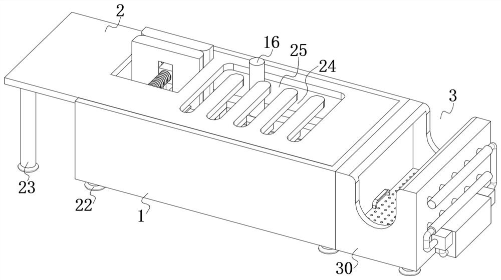
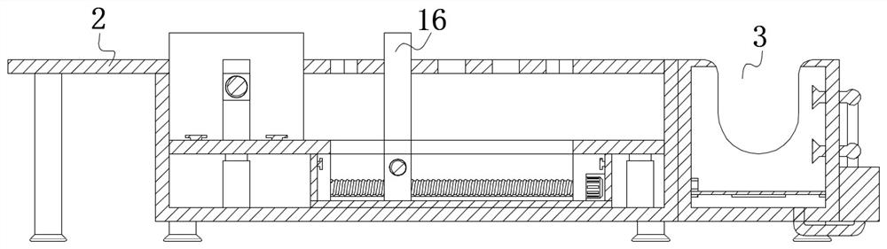
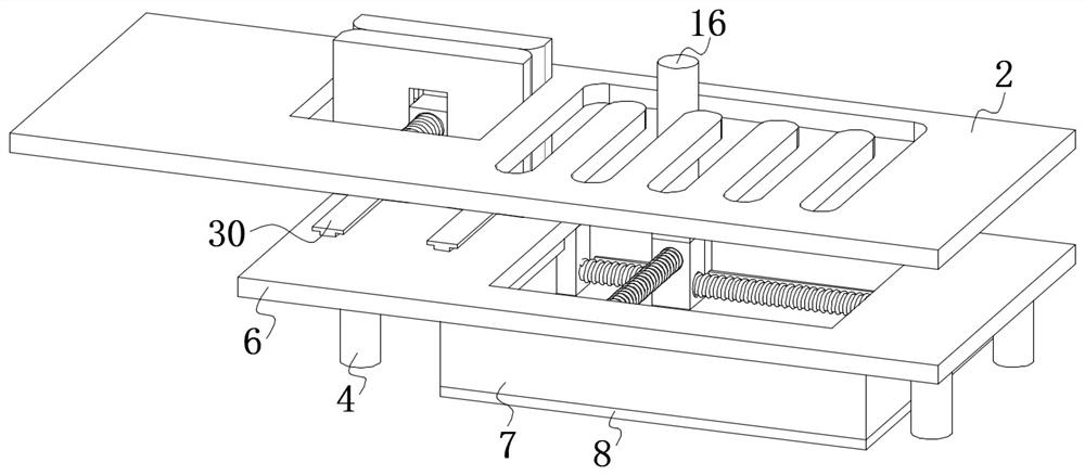
[0033] see Figure 1-8, the present invention provides a multi-angle metal bending device for auto parts processing, comprising an outer box 1, the inner wall of the outer box 1 is fixedly connected with a worktable 2; the worktable 2 is a work console, and when bending metal, The bending operation will be performed on the work surface 2; the outer box 1 is fixedly connected with a cooling mechanism 3; the inner wall of the outer box 1 is fixedly connected wi...


PUM


Abstract

The invention discloses a multi-angle metal bending device for automobile part machining, and belongs to the technical field of metal machining. The device comprises an outer box body, and the inner wall of the outer box body is fixedly connected with a working table; one surface of the outer box body is fixedly connected with a cooling mechanism; the inner wall of the outer box body is fixedly connected with one ends of a group of electric telescopic rods which are distributed in a rectangular array; the other ends of the group of electric telescopic rods are fixedly connected with an adjusting mechanism; the adjusting mechanism comprises a lifting plate; the lower surface of the lifting plate is fixedly connected with an outer frame body; the lower surface of the outer frame body is fixedly connected with a bottom plate; the inner wall of the outer frame body is slidably connected with a bending assembly; the bending assembly comprises two sliding plates a; and one surface of one ofthe sliding plates a is rotationally connected with a threaded screw rod a. According to the multi-angle metal bending device, through the design of a fixed clamping plate, a sliding clamping plate, athreaded lead screw c and a threaded seat, the device can conduct full-automatic bending on strip-shaped metal of various different sizes, the cooling function is achieved, and therefore the machining efficiency of metal parts and the safety in the machining process are improved.

Description

technical field [0001] The invention belongs to the technical field of metal processing, and in particular relates to a multi-angle metal bending device for processing automobile parts. Background technique [0002] my country's latest national standard "Terms and Definitions of Vehicles and Trailer Types" has the following definitions for vehicles: non-track-bearing vehicles driven by power and with 4 or more wheels, mainly used for: carrying people and (or) Goods; vehicles that tow and carry people and / or goods. In the production process of automobiles, the auto parts must first be produced and processed. Among the auto parts, there are a large number of metal parts. During the production and processing of metal parts , it is necessary to use a bending device to bend metal parts. [0003] In the process of bending metal, the existing metal bending device often needs manual auxiliary operation, and it is difficult to achieve fully automatic mechanical operation, which leads ...

Claims


Application Information

Patent Timeline
IPC IPC(8): B21D7/06B21D7/16B21D37/04B21D43/00
CPCB21D7/06B21D7/16B21D7/165B21D37/04B21D43/003
Inventor 唐秀恰
Owner 宁波曼汶智能装备有限公司
Why Eureka
Try Eureka