Rotary impact tool
A technology of impact tools and tools, applied in the field of rotary impact tools, can solve problems such as damage to mechanical components
- Summary
- Abstract
- Description
- Claims
- Application Information
AI Technical Summary
Problems solved by technology
Method used
Image
Examples
no. 1 Embodiment approach
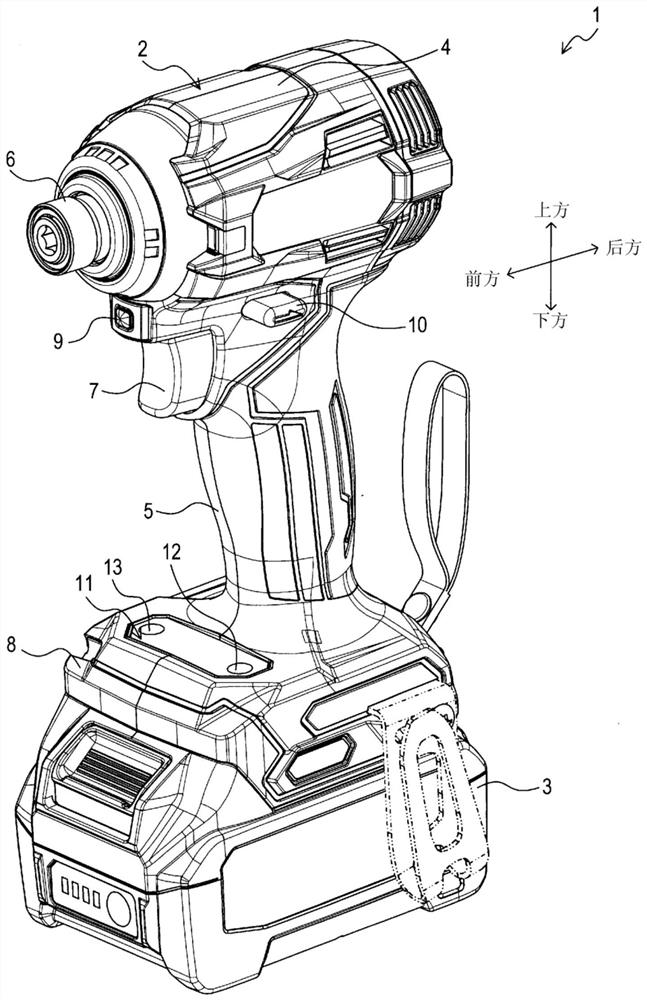
[0046] The following is attached Figure 1 The first embodiment of the present disclosure will be described first.
[0047] The impact driver 1 of the present embodiment is used to fix bolts, nuts, and the like to an object.
[0048] Such as figure 1 As shown, an impact driver 1 includes a tool body 2 and a battery pack 3 . The battery pack 3 is detachably attached to the tool body 2 to supply electric power to the tool body 2 .
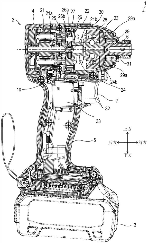
[0049] The tool main body 2 includes: a housing 4 , a handle 5 , a chuck cover 6 , a trigger 7 , a battery mounting portion 8 , a mode switching switch 9 , a forward and reverse switching switch 10 , and an operation panel 11 .
[0050] The case 4 accommodates a motor 21 , an impact mechanism 23 , and the like which will be described later.
[0051] The handle 5 is disposed below the housing 4 . The handle 5 is shaped so that a user of the impact driver 1 can hold the handle 5 with one hand.
[0052] The chuck sleeve 6 is disposed in front of t...
no. 2 Embodiment approach
[0236] The following is attached Figure 1 First, the second embodiment of the present disclosure will be described. In addition, in 2nd Embodiment, the part which differs from 1st Embodiment is demonstrated. Common structures are assigned the same reference numerals.
[0237] The impact driver 1 of the second embodiment differs from the first embodiment in that the program of the output limitation process is changed.
[0238] Such as Figure 13 As shown, the output restriction processing of the second embodiment differs from the first embodiment in that the processing of S240 and S250 is omitted and the processing of S270, S280, and S290 is added.
[0239] That is, when the processing of S230 ends, the CPU 56a calculates the limit sum value in S270. Specifically, the CPU 56a first stores a product value obtained by multiplying the value stored in the current difference Current_Diff by the preset summed rotational speed gain INC_Speed_Gain in the summed rotational speed IN...
no. 3 Embodiment approach
[0243] The following is attached Figure 1 The third embodiment of the present disclosure will be described first. In addition, in the third embodiment, the parts different from the first embodiment will be described. Common structures are assigned the same reference numerals.
[0244] The impact driver 1 of the third embodiment differs from the first embodiment in that the configuration of the tool body 2, the configuration of the control circuit 56, and the program of the output limiting process are changed.
[0245] Such as Figure 14 As shown, the tool body 2 includes a torque sensor 42 . The torque sensor 42 detects the torque applied to the output shaft 21a of the motor 21, and outputs a torque detection signal indicating the detection result.
[0246] The control circuit 56 further includes a torque calculation unit 77 as a functional block realized by software processing executed by the CPU 56 a. The torque calculation unit 77 calculates a torque value based on th...
PUM
 Abstract
Description
Claims
Application Information
 - R&D
- Intellectual Property
- Life Sciences
- Materials
- Tech Scout
- Unparalleled Data Quality
- Higher Quality Content
- 60% Fewer Hallucinations
Browse by: Latest US Patents, China's latest patents, Technical Efficacy Thesaurus, Application Domain, Technology Topic, Popular Technical Reports.
© 2025 PatSnap. All rights reserved.Legal|Privacy policy|Modern Slavery Act Transparency Statement|Sitemap|About US| Contact US: help@patsnap.com


