
Pulse magnetic shock catapult

A catapult, pulse magnetic technology, applied in the direction of launch/drag transmission, etc., can solve the problems of difficult application of electromagnetic catapult, high technical difficulty, harsh power, etc., to reduce brush consumption, low technical difficulty, and reduce pulse effect of magnitude

Pending Publication Date: 2021-03-30
肖瑞文
View PDF8 Cites 0 Cited by
  • Summary
  • Abstract
  • Description
  • Claims
  • Application Information

AI Technical Summary

Problems solved by technology

However, the power supply devices of the electromagnetic catapult systems used by existing non-nuclear-powered aircraft carriers are all permanent magnet linear synchronous motors, which have the disadvantages of complex structure, high technical difficulty, and particularly harsh requirements for electric power, requiring strong electric energy. The industry generally believes that It is difficult to apply electromagnetic catapults to non-nuclear powered aircraft carriers, and it is necessary to improve
In the Chinese patent database, there is no pulse magnetic shock catapult applied to eject aircraft carrier

Method used


Image

  • Pulse magnetic shock catapult
  • Pulse magnetic shock catapult
  • Pulse magnetic shock catapult

Examples


Embodiment

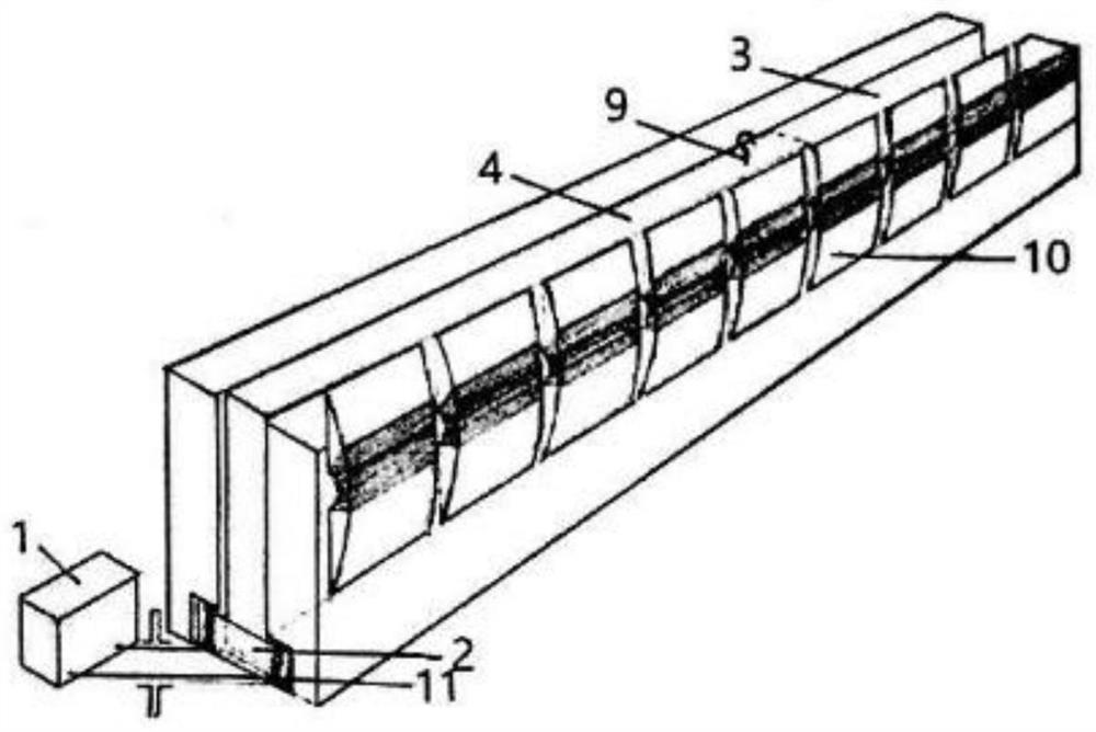
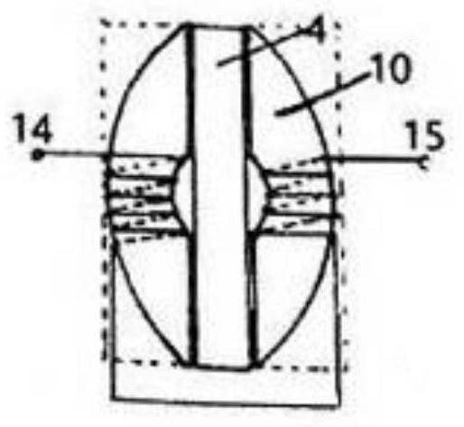
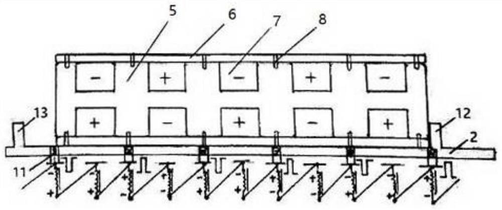
[0033] Embodiment: A kind of pulse magnetic shock catapult for aircraft carrier

[0034] A kind of pulse magnetic shock catapult used for carrier-based aircraft as shown in accompanying drawing, 2, 3, is arranged on the second half of the skid deck of aircraft carrier, comprises power supply 1, the power supply control panel 2 that is connected with power supply 1, and The U-shaped ejection guide rail 3 connected to the power supply control board 2, and the ejection tractor 4 arranged on the U-shaped ejection guide rail 3 and slidingly connected with the U-shaped ejection guide rail 3, the U-shaped ejection guide rail 3 and the ejection tractor 4 form a high thrust density The linear propulsion device, the carrier-based aircraft waiting for ejection straddles the U-shaped ejection guide rail 3. The front end of the power supply control board 2 is provided with an ejection lock pile 12, which is used to limit the farthest position of the ejection retractor 4 sliding to the fron...


PUM


Abstract

A pulse magnetic shock catapult comprises a power supply, a power supply control panel, a U-shaped catapult guide rail connected with the power supply control panel and a catapult tractor arranged onthe U-shaped catapult guide rail in a sliding connection mode, the catapult tractor is a sliding block of a frame structure, and at least four pairs of magnets which are symmetrically arranged up anddown and have alternate positive and negative magnetic poles are embedded in the sliding block; silicon steel sheet winding unit arrays formed by connecting windings in series in the length directionare symmetrically embedded in the left side wall and the right side wall of the U-shaped catapult guide rail; each silicon steel sheet winding unit comprises two oppositely-arranged coils, the power supply supplies power to the silicon steel sheet winding unit to generate a magnetic field, and the power supply is a super-power variable-frequency pulse generator. The catapult is simple in structure, low in technical difficulty, low in manufacturing cost, convenient to maintain and remarkable in energy conservation. Under the same condition, compared with an existing electromagnetic catapult using a permanent magnet linear synchronous motor, energy is saved by at least 40%. Power is supplied in a ground-wire-free mode, the pulse amplitude can be reduced, the consumption of an electric brushis reduced, and a ground wire is omitted.

Description

technical field [0001] The invention relates to an object ejection device, in particular to a pulse magnetic shock ejector. Background technique [0002] Electromagnetic catapult technology is an emerging energy catapult linear propulsion technology, which belongs to one of the core technologies of aircraft carrier (hereinafter referred to as aircraft carrier). Electromagnetic energy is used to propel the ejected object outward in a straight line, and the ejected object does not use its own power device but relies on the starting force given by the catapult to take off. It is suitable for short-range launching such as an aircraft carrier with a weight of nearly 30 tons. Accelerating to a take-off speed of more than 140 knots within a distance of less than 100 meters has wide application prospects in military, civil and industrial fields. The electromagnetic catapult used by the existing carrier-based aircraft generates Lorentz force by laying and fixing the non-movable ener...

Claims


Application Information

Patent Timeline
Patent Type & Authority Applications(China)
IPC IPC(8): B64F1/06
CPCB64F1/06
Inventor 肖瑞文
Owner 肖瑞文
Learn More