Air supply system and method for pneumatic valve executing mechanism

A technology of pneumatic valves and actuators, which is applied in the pipeline system, engine components, valve operation/release devices, etc., and can solve the problems that the compressed air buffer tank cannot realize automatic high-pressure energy storage, slow response, and difficulty in ensuring reliable air supply, etc.

Pending Publication Date: 2021-03-30
CHINA NUCLEAR POWER ENG CO LTD
View PDF7 Cites 0 Cited by
  • Summary
  • Abstract
  • Description
  • Claims
  • Application Information

AI Technical Summary

Problems solved by technology

[0004] In order to at least partially solve the technical problems that the compressed air buffer tank in the prior art cannot realize automatic high-pressure energy storage, slow response, and difficult to ensure reliable air supply, the present invention is completed

Method used


Image

  • Air supply system and method for pneumatic valve executing mechanism
  • Air supply system and method for pneumatic valve executing mechanism
  • Air supply system and method for pneumatic valve executing mechanism

Examples


Embodiment Construction

[0037] In order to enable those skilled in the art to better understand the technical solutions of the present invention, the present invention will be further described in detail below in conjunction with the accompanying drawings and embodiments.

[0038] It should be noted that, in the case of no conflict, the embodiments of the present invention and the features in the embodiments can be combined arbitrarily with each other.

[0039]Wherein, the terms used in the embodiments of the present invention are only for the purpose of describing specific embodiments, and are not intended to limit the present disclosure. As used in the embodiments of the present invention and the appended claims, the singular forms "a", "said" and "the" are also intended to include plural forms unless the context clearly indicates otherwise.

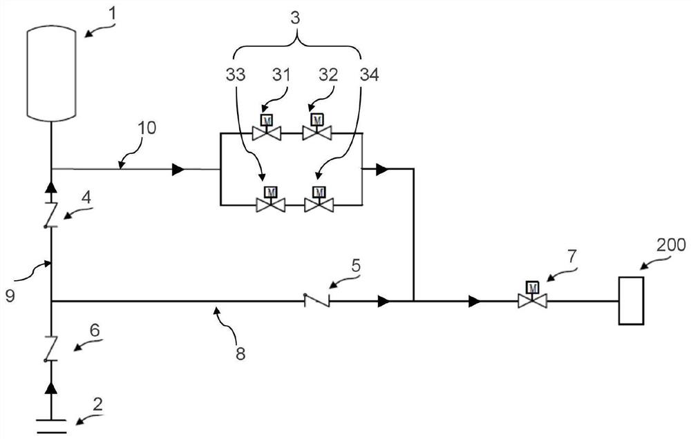
[0040] like figure 1 As shown, the embodiment of the present invention provides an air supply system for a pneumatic valve actuator, which is connected to t...


PUM


Abstract

The invention provides an air supply system and method for a pneumatic valve executing mechanism. The system comprises a compressed air interface, a compressed air buffer tank, and an air supply valvebank, wherein the compressed air interface is connected to the pneumatic valve executing mechanism through a normal air supply pipeline, and is connected to the compressed air buffer tank through aninflating air supply pipeline to supply air to the compressed air buffer tank; the compressed air buffer tank is connected to the pneumatic valve executing mechanism through a standby air supply pipeline; the air supply valve bank is arranged on the standby air supply pipeline, and is closed when the compressed air is normal and is opened when the compressed air is abnormal, such that the compressed air buffer tank supplies air to the executing mechanism; a first check valve is arranged on the inflating air supply pipeline, and a second check valve is arranged on the normal air supply pipeline; and inlet sides of the first and second check valves are sides close to the compressed air interface. The system and method can be used for achieving automatic high pressure energy storage of the compressed air buffer tank, and supplies air to the executing mechanism automatically under an emergent circumstance, such that the air supply system of the pneumatic valve executing mechanism is higherin reliability and safety.

Description

technical field [0001] The invention belongs to the technical field of mechanical control, and in particular relates to an air supply system for a pneumatic valve actuator and an air supply method for a pneumatic valve actuator. Background technique [0002] In the process of nuclear engineering design, many fluid mechanical systems use electric valves to achieve isolation functions. However, due to the inherent characteristics of electric actuators, electric valves take a relatively long time to close the valves. In some engineering designs with special safety requirements Not available. Therefore, many fluid mechanical systems use pneumatic valves in order to achieve fast closing and regulating functions. However, whether these pneumatic valves can reliably achieve their functions and whether they can operate for a long time depends on the air supply to these pneumatic valve actuators. Whether the air system is reliable and its air supply time; especially in the event of ...

Claims


Application Information

Patent Timeline
Patent Type & Authority Applications(China)
IPC IPC(8): F16K31/12F17D1/07F17D1/02F17D3/01
CPCF16K31/12F17D1/07F17D1/02F17D3/01
Inventor 赵嘉明王晓江侯婷杨轶方立强李亚飞齐实李嫦月于沛赵斌
Owner CHINA NUCLEAR POWER ENG CO LTD
Why Eureka
Try Eureka