[0024] Embodiments of the present invention will be described in detail below, and examples of the embodiments are illustrated in the drawings, in which the same or similar reference numerals represent the same or similar elements or elements having the same or similar functions. The following is exemplary, and is intended to be used to illustrate the invention without understanding the limitation of the invention.
[0025] In the description of the present invention, it is to be understood that the orientation or positional relationship indicated by "upper", "lower", "top", "bottom", "inside", "outside", etc. is based on the drawings. The orientation or positional relationship is intended to facilitate the description of the present invention and simplified description, rather than indicating or implying that the referred to means must have a particular orientation, and therefore, it is not understood to be limited to the present invention.
[0026] In the present invention, the terms "installation", "connected", "connection", "fixed", such as the term "mount", "connected", "linked", "fixed", unless otherwise expressly specifically understood, for example, can be a fixed connection, or a detachable connection One integration; may be mechanical connection, or may be electrically connected or can communicate with each other; may be directly connected, or indirectly connected by an intermediate medium, which may be an interaction between two elements or two elements. For those skilled in the art, the specific meaning of the above terms can be understood in terms of specific cases.
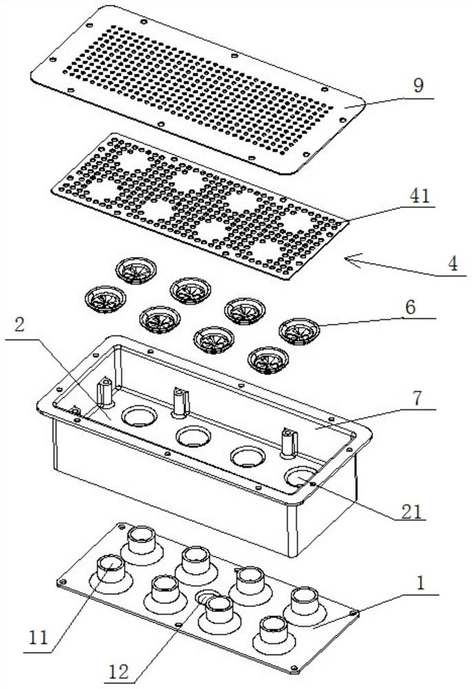
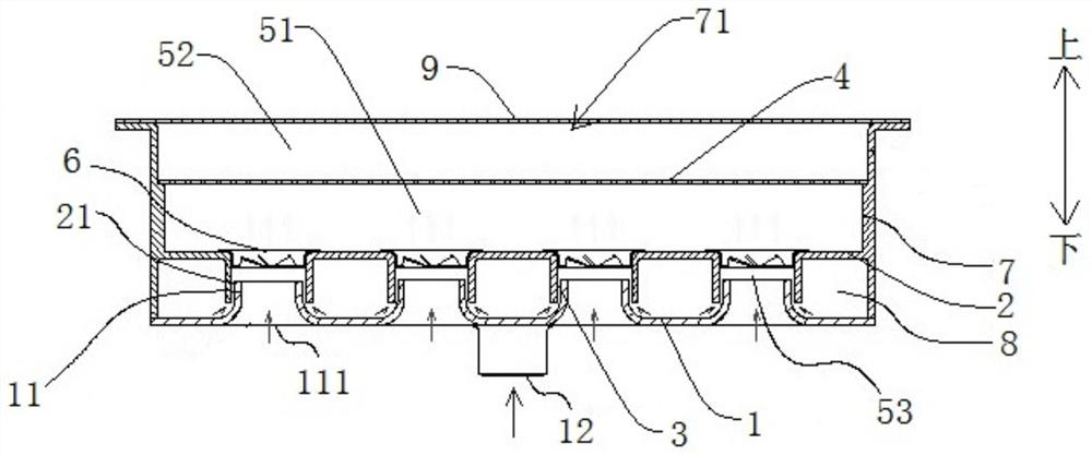
[0027] Bonded below Figure 1 - Figure 2 A premixing device for combustion heat exchange apparatus according to an embodiment of the present invention will be described in detail.
[0028] Refer Figure 1 - Figure 2 As shown, the premixing device for the combustion heat exchange apparatus according to the embodiment of the present invention includes: a cavity, a cavity having an air inlet 111, a gas inlet 12, and a mixed air outlet 71, air from the air inlet 111 into the cavity The gas is entered from the gas inlet 12 into the cavity, and the air is mixed in the cavity in the cavity and then discharged from the mixture air outlet 71 to ensure that the combustion heat exchange device can completely combust the gas, thereby increasing the utilization efficiency of gas, reducing the harmful gas Emissions.
[0029] Further, such as figure 2 As shown, an air intake pipe 11 is provided in the cavity, and the mixing plate 2 and the dispensing plate 4 are located, and the dispensing plate 4 is located on one side of the air intake pipe 11 and the mixing plate 2, specifically, mixed air. The air inlet 71 is located on one side of the dispensing plate 4, and the air inlet 111 is located on the other side of the dispensing plate 4, and a plurality of mixed air dispensing holes 41 are provided on the dispensing plate 4, and when the gas mixture is distributed When the plate 4, the gas mixture can pass through the dispensing plate 4 from the plurality of mixed air dispensing holes 41. When the gas mixture passes through the dispensing plate 4, the distribution plate 4 can uniformly dissipate the gas mixture, thereby making the gas mixture uniform. Flooding at the mixed air outlet 71, thereby providing advantageous conditions for the combustor 9 to fully combust the gas mixture to ensure high heat exchange efficiency of the combustion heat exchange device, thereby effectively reducing the content of the harmful gas in the combustion heat exchange device.
[0030] Further, such as figure 2 As shown, the inlet end of the air intake pipe 11 constitutes an air inlet 111, and the gas inlet 12 is located at the same side of the mixing plate 2, and the mixing plate 2 is provided with a premixing tube 21, and the air intake pipe 11 is at least partially. Set within the premixing tube 21, there is a gap between the air intake pipe 11 and the premix tube 21 to form a gas intake passage 3, the gas intake passage 3 communicates with the outlet end of the gas inlet 12 and the premixing tube 21.
[0031] Specifically, the air enters the air intake pipe 11 after the air inlet 111, and the gas is entered from the gas intake passage 3 between the premixing tube 21 and the air intake pipe 11 from the gas inlet 12 into the total. The premoxic region is achieved to achieve contact, mixing with air.
[0032] In the specific embodiment, if Figure 1 - Figure 2 As shown, the air intake pipe 11 is sleeved in the premixing tube 21, and the direction of the air intake passage 3 is the same as the air intake pipe 11 of the air intake pipe 11, and therefore, when the gas is supplied from the gas intake passage 3 When discharged, in the inertia of air high-speed, the gas can have a certain impact force, thereby turning the gas into a turbulence, so that the gas can be integrated into the air, then enter the total premix area, air and gas The flow rate is lowered, and the air is free to diffuse, so that the air can be further mixed with the gas to ensure that the gas is mixed with air, which in turn can ensure that the gas mixture has high combustion efficiency, which is advantageous to reduce the combustion heat transfer equipment. At work, the exhausted harmful gas is less.
[0033] The air intake pipe 11, the mixing plate 2, and the mating structure of the dispensing plate 4 are simple, not only ensuring that the premixing effect of air and the gas can be ensured that the cost of the premixing device is low.
[0034]According to an embodiment of the present invention, a premixing device for combustion heat exchange means is provided with a premix tube 21, and the air intake pipe 11 is partially set within the premixing tube 21, and the air intake pipe 11 and the pre-pre-pre- When the gap between the mixing tube 21, the gas intake passage 3 is discharged from the gas intake passage 3, the air in the air intake pipe 11 can generate a force to the gas, thereby mixing the gas into the air, and dispensing the plate. 4 can uniformly dissipate the gas mixture, so that the gas mixture is uniformly flooded at the mixed air outlet 71, which in turn can ensure that the gas mixture is highly combustion efficiency, which is advantageous to reduce the combustion heat exchange equipment at work. The exhausted harmful gas. Further, the air intake pipe 11, the mixing plate 2, and the mating structure of the dispensing plate 4 are simple, not only ensures that the premixing of air and the gas is better, but also the cost of the premixing device is low.
[0035] Further, such as figure 2 As shown, the mixture plate 2 forms a first premixing region 51 between the dispensing plate 4, and the dispensing plate 4 forms a second premixing region 52 between the mixed air outlet 71, and the mixture distribution hole 41 functions. District 51 and the second premixing region 52.
[0036] It should be noted that the term "first", "second" is used only for the purpose of describing purposes, and cannot be understood as an indication or implies relative importance or implicitting the number of techniques indicated. Thereby, the features of "first", "second" may be defined, and one or more of this feature may be further included. In the description of the invention, the meaning of "plurality" is at least two, such as two, three, etc., unless otherwise specifically defined.
[0037] In a specific embodiment, when air is entered into the first premix region 51, since the space is suddenly expanded, the flow rate of air and gas is rapidly reduced, and the air can be mixed with the gas, which facilitates improving the degree of mixing of air and gas. Subsequently, the gas mixture enters the second premixing region 52 from the mixture distribution hole 41, and the distribution plate 4 is uniformly dissipated, and when the air and gas can be performed again when it enters the second premixing region 52. Mixing to ensure uniform mixing of air and gas, and, the mixed gas mixture can be uniformly flooded at the mixed air outlet 71.
[0038] Further, the mixture dispensing hole 41 is configured with the air outlet of the premixing tube 21, which can increase the path of the mixed gas in the first premixing region 51, thereby preventing gas mixing air from passing through the wind pressure of the exhaust. The mixture dispensing hole 41 causes a poor mixture of air and gas.
[0039] Further, such as Figure 1 - Figure 2 As shown, a swirling blade 6 is provided in the premixing tube 21, and a third premixing region 53 is formed between the outlet end of the air intake pipe 11 and the swirl blade 6.
[0040] The swirl blades 6 can be rotated under the action, and therefore, a swirling blade 6 is provided in the premixing tube 21, and it is possible to further improve the effect of gas mixing with the air. Further, there is a gap between the outlet end of the air intake pipe 11 and the swirl blades 6 to form a third premixing region 53, which provides a space to the air with the air.
[0041] Further, the air intake pipe 11 is a plurality of swirl blades 6, and the premixing tube 21 corresponds to the air intake pipe 11. Therefore, when air enters into the cavity, the air is uniformly flowing into the respective air intake pipes 11, and the gas flows out from each corresponding gas intake passage 3, thereby not only reduce the flow rate of intake air, not only. It is guaranteed that the air resistance is small, and the mixing effect of air and gas can also be improved.
[0042] Preferably, the plurality of air intake pipes 11 are uniformly arranged, thereby facilitating ensuring uniform air volume of the respective air intake pipes 11, which further benefits the mixing effect of gas and air.
[0043] In the specific embodiment, if figure 2 As shown, the gas and air will perform initial contact, mix, and, under the action of air and gas flow inertia, and therefore, when air and gas are passed through the flow inertia of air and gas. When the swirling blade 6, the flow blade 6 will stir the gas to air, so that the gas can be mixed into the inside of the air, and the mixing effect of gas and air can be further improved, and the gas and air will enter the first In the premix region 51, in the second premixing region 52, the gas and air are in contact with the second premixing region 52 again, and to ensure that the gas is mixed with air.
[0044] Further, such as Figure 1 - Figure 2 As shown, the premixing device can include: the mixture fixing seat 7 and the intake base 1, the mixture fixing seat 7 is located above the intake base 1, and the mixture fixing seat 7 is enclosed in a cavity, air into the air. The air pipe 11 is located on the intake base 1, and the gas inlet 12 is formed on the intake base 1, and the air intake pipe 11 is sturdy, and the mixture air outlet 71 is located at the top of the mixed retaining seat 7, that is, mixed air The fixing seat 7 has a hollow cavity having a port on both sides, and the bottom surface of the mixture fixing seat 7 is fitted to the intake base 1 to enclose the cavity, the intake pipe is located on the intake base 1, and the gas inlet 12 is formed. On the intake base 1, the top surface of the mixed fixing seat 7 forms a mixed air outlet 71.
[0045] Further, the mixing plate 2 is located in the mixed retaining seat 7, and the mixing plate 2 is located above the intake base 1, thereby ensuring that the gas can be mixed with the air in the third premixing region 53.
[0046] Specifically, the mixing wall of the adjacent two premix tubes 21 is aligned with the base connection wall of the adjacent two air intake pipe 11, to form a hollow portion 8 between the connecting wall connecting the wall connecting wall and the base connection wall. The gas inlet 12 is in communication with the hollow portion 8 through the gas intake passage 3.
[0047] Therefore, when the gas can be stored, the gas can be temporarily stored in the hollow portion 8, and when the gas in the hollow portion 8 is full, the gas that is continuously flowing into the hollow portion 8 can squeeze the gas stored in the hollow portion 8. Each gas intake passage 3 thus enables all gas intake passages 3 to flow out, which in turn ensures that the effect of air and gas mixing is better.
[0048] Further, the air intake pipe 11 is a linholic tube, and the inlet segment of the air intake pipe 11 is facing the outside, and the air inlet 111 of the air intake is formed, and the diffusion section of the air intake pipe 11 is toward the top surface of the mixed retaining seat 7, therefore, The air intake pipe 11 is a Wenqi tube. When the air passes through the air intake pipe 11, the flow rate of the air can be improved, so that the air of the air can increase the impact force of the gas, and further improve the mixing effect of air and gas.
[0049] According to another aspect of the invention, a combustion heat exchange apparatus comprising the above-described premixing device, a combustor 9, a fan, and a heat exchanger, a combustor 9 located in a premixing device. At 71, the air inlet of the fan is connected to the mixed air outlet 71 of the premixing device, and the heat exchanger is located above the combustor 9, and the heat exchanger is connected to the water pipe and the water pipe.
[0050] It should be noted that the fan is a non-necessary member. When the combustion heat transfer device has a fan, the combustion of the fire is discharged from the combustion heat transfer device by the fan; when the combustion heat exchange device does not have a fan, the combustion will be burned by natural wind. The latter exhaust gas is discharged from the combustion heat exchange equipment.
[0051] In a particular embodiment, the combustion heat exchange device can be a gas water heater, a gas wall mounting furnace, or the like, and the following is an example of a gas water heater, specifically, the working process of the combustion heat exchange device, wherein the fan water collector is assumed.
[0052] The heat exchanger has a heat transfer portion for transmitting heat in the heat exchanger to cold water, which is heated, specifically, the water pipe and the water tube are connected, the water pipe is connected to the faucet or other water outlet, water pipe The cold water in which the cold water passes through the heat exchanger from the water pipe, thereby achieving the gas water heater to heat the cold water to satisfy the user's use of hot water.
[0053] Further, the heat exchanger is at least partially located above the burner 9, and the combustor 9 can combust to the gas, and then release heat, and therefore, the heat exchanger is at least partially located above the catalytic burner 9 can be released. The heat is fully absorbed.
[0054] Specifically, in a gas water heater of cold water heating using a catalytic burner 9, the combustor 9 can include a preheating burner 9 and a catalytic burner 9, a preheating burner 9 and a catalytic burner 9, preheating burner 9 Used in the preheating catalytic burner 9, the catalytic burner 9 and the preheating burner 9 can combust the gas in combustion, wherein the preheating burner 9 is an open fire combustion, the preheating burner 9 is a flameless combustion, in the specific In an embodiment, a portion of the heat generated by the preheated burner 9 is used for heating the heat exchanger, and the other portion is used to heat the catalytic burner 9, and therefore, the preheating combustor 9 is relatively arranged to catalytic burner 9, which can make catalysis The burner 9 can enter the working state as soon as possible, and when the combustor 9 is catalyzes a certain temperature, the open flame on the preheating burner 9 is extinguished, and the gas is a self-suction flameless combustion, catalytic burner 9 on the catalytic burner 9. The heat released by the combustion can maintain the lifting temperature required for the catalytic burner 9 itself, and on the other hand, heat exchanger is heated, and the flame is more soft and smooth, and the noise is low, thereby ensuring the gas water heater at work. Friendly is more friendly in the external environment, thereby ensuring the use of gas water heaters more environmentally friendly and safe and comfortable.
[0055] In a specific embodiment, when the gas water heater starts working, the air enters the air intake pipe 11 from the plurality of air inlet 111, while the gas begins to supply, the gas flows into each gas intake passage 3, air and gas in the third The premixing region 53 is initially mixed, and the gas is stirred with air under the rotation of the swirl blades 6, and then all gas and air are aggregated in the second premixing region 52 to carry out another mix, and the distribution plate 4 pair After the gas mixing is dispersed, the final mixing is performed at the first premixing region 51, and finally the mixed gas mixture is uniformly discharged from the mixed air outlet 71, and the preheating burner 9 is ignited after mixing gas mixing, while The heat exchanger is heated with the catalytic burner 9. When the catalytic burner 9 reaches the operating temperature, the preheating burner 9 stops working, the catalytic burner 9 continues to heat the heat exchanger, thereby the heat exchanger Heating is performed to ensure that the gas water heater has continuously hot water to complete the heating process of the gas water heater.
[0056] It should be noted that the premixing device can not only be used in the gas water heater, but also mixed with air, but also in other combustion heat exchange devices, for example, in nitrogen vehicles, the premixing device can be mixed with air. .
[0057] In the description of the present specification, the description of the reference terms "one embodiment", "some embodiments", "example", "specifically example" or "some example", etc., meant to combine the specific features described in connection with the example, Structure, material or characteristics are included in at least one embodiment or example of the present invention. In the present specification, schematic representations of the above terms are not necessarily directed to the same embodiments or examples. Moreover, the specific features, structures, materials or features described may be combined in any one or more embodiments or examples. Moreover, those skilled in the art can engage and combine different embodiments or examples described in this specification.
[0058] Although the embodiments of the present invention have been shown and described above, it is understood that the above embodiments are exemplary, and cannot be understood as limiting the invention, and those of ordinary skill in the art can be described above. EXAMPLES Change, modify, replace, and variants.