Photoelectric piezoelectric electrostatic composite driving micro-mirror fine adjustment device

An electrostatic composite and micro-adjustment technology, applied in optics, optical components, instruments, etc., can solve problems such as inability to directly operate control, lack of adaptability, etc., achieve fast response, good effect, and realize the effect of displacement adjustment

Inactive Publication Date: 2021-03-30
南通速图科技有限公司
View PDF3 Cites 1 Cited by
  • Summary
  • Abstract
  • Description
  • Claims
  • Application Information

AI Technical Summary

Problems solved by technology

The traditional micromirror table is driven by mechanical transmission such as precision screw pair and rolling guide rail, precision spiral wedge mechanism, turbine-concave mechanism, gear-lever mechanism, etc. Due to mechanical friction, clearance, crawling and other reasons, it is difficult to Successful one-time positioning often requires fine-tuning, and there are also defects such as insufficient adaptability to electric heating, electromagnetic and other driving forms. At the same time, it cannot be directly operated and controlled in a vacuum or in a specific operating environment. Therefore, we propose a photovoltage electrostatic Composite drive micromirror fine-tuning device

Method used


Image

  • Photoelectric piezoelectric electrostatic composite driving micro-mirror fine adjustment device
  • Photoelectric piezoelectric electrostatic composite driving micro-mirror fine adjustment device
  • Photoelectric piezoelectric electrostatic composite driving micro-mirror fine adjustment device

Examples


Embodiment Construction

[0015] The following will clearly and completely describe the technical solutions in the embodiments of the present invention with reference to the accompanying drawings in the embodiments of the present invention. Obviously, the described embodiments are only some, not all, embodiments of the present invention. Based on the embodiments of the present invention, all other embodiments obtained by persons of ordinary skill in the art without making creative efforts belong to the protection scope of the present invention.

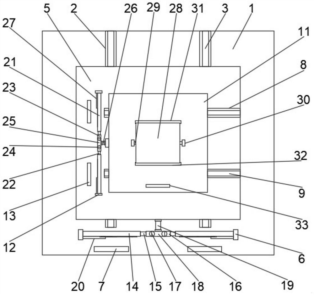
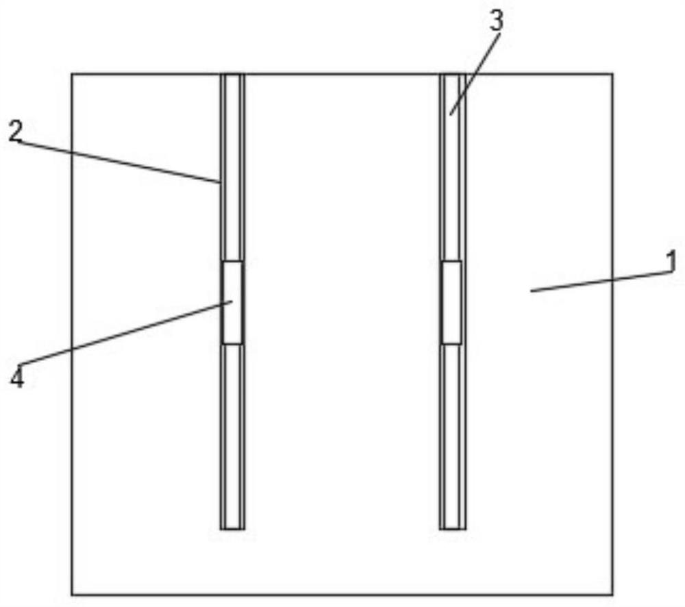
[0016] see Figure 1-3 , the present invention provides a technical solution: a micro-mirror micro-adjustment device driven by a photovoltage-electric-electrostatic compound, including a coarse motion table 1, and a Y-direction slide rail 2 is symmetrically provided on the coarse motion table 1, and the Y-direction slide A first slide bar 3 is provided inside the rail 2, and the first slide bar 3 is slidably connected with the Y-direction fine-tuning platform ...


PUM


Abstract

The invention discloses a photoelectric piezoelectric electrostatic combined drive micro-mirror fine adjustment device. The device comprises a coarse movement table; Y-direction sliding rails are symmetrically arranged on the coarse movement table; first sliding rods are arranged in the Y-direction sliding rails; the first sliding rods are in sliding connection with a Y-direction fine adjustment platform through first sliding blocks; A Y-direction adjusting mechanism is arranged below the Y-direction fine adjustment platform and located on the surface of the coarse movement table; the two endsof the Y-direction adjusting mechanism are fixedly connected to the surface of the coarse movement table through first fixing blocks; Y-direction photoelectric ceramics are symmetrically arranged below the Y-direction adjusting mechanism and located on the surface of the coarse movement table; light energy is converted into electric energy through the photo-generated voltage effect of the photoelectric ceramics; the electric energy is converted into mechanical energy through the inverse piezoelectric effect of a piezoelectric film on a piezoelectric film driver in the adjusting mechanism, sothat displacement adjustment can be achieved. The device is simple and compact, and higher in response speed.

Description

technical field [0001] The invention relates to the technical field of micro-mirror micro-adjustment driving, and specifically relates to a micro-mirror micro-adjustment device for photoelectric-voltage-electrostatic composite drive. Background technique [0002] Micromirrors are widely used in defense and civilian fields such as optical systems, micro-mechanical optical switches, precision measurement, medical imaging, biotechnology, and aerospace. In recent years, the modulation of the intensity and phase of the incident light and the gating of the optical path can be realized by equipping the micromirror with driving devices with different functions, so that the micromirror has functions such as optical switching and adaptive optics correction. The traditional micromirror table is driven by mechanical transmission such as precision screw pair and rolling guide rail, precision spiral wedge mechanism, turbine-concave mechanism, gear-lever mechanism, etc. Due to mechanical f...

Claims


Application Information

Patent Timeline
Patent Type & Authority Applications(China)
IPC IPC(8): G02B26/08
CPCG02B26/0858G02B26/0841
Inventor 秦毅宋立武曹金龙李春龙
Owner 南通速图科技有限公司
Why Eureka
Try Eureka