
A Nonlinear Substructure Method Applicable to Modeling Complex Large Flexible Aircraft

A nonlinear, aircraft technology, applied in the field of structural dynamics, can solve the problems of high modeling cost and low calculation efficiency, and achieve the effect of speeding up the design progress, reducing the amount of analysis and calculation, and improving the calculation and design efficiency.

Active Publication Date: 2022-08-05
BEIHANG UNIV
View PDF5 Cites 0 Cited by
  • Summary
  • Abstract
  • Description
  • Claims
  • Application Information

AI Technical Summary

Problems solved by technology

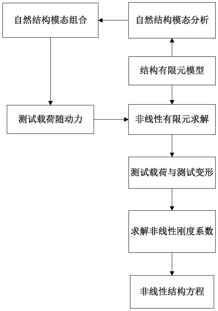
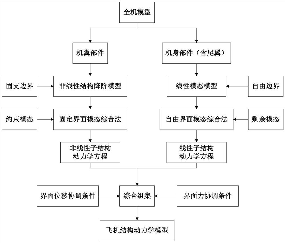
[0007] In order to overcome the problems of high modeling cost and low calculation efficiency of the traditional structural modeling method in large flexible and complex aircraft models, the present invention performs structural modeling and calculation analysis of complex models based on nonlinear structural reduction model and modal synthesis method, Using the idea of ​​the substructure method, the wing components are modeled as geometrically nonlinear components using the nonlinear structural reduction model, and the fuselage components are modeled as linear components using linear modal modeling. Finally, the modal synthesis method is used to coordinate the interface The conditions are regrouped to form the whole machine structure model, and an efficient and accurate geometric nonlinear structural modeling analysis method for large flexible aircraft is proposed, which can further reduce the structural modeling cost of complex large flexible aircraft models, and improve the modeling and structure Analysis efficiency

Method used


Image

  • A Nonlinear Substructure Method Applicable to Modeling Complex Large Flexible Aircraft
  • A Nonlinear Substructure Method Applicable to Modeling Complex Large Flexible Aircraft
  • A Nonlinear Substructure Method Applicable to Modeling Complex Large Flexible Aircraft

Examples


Embodiment 1

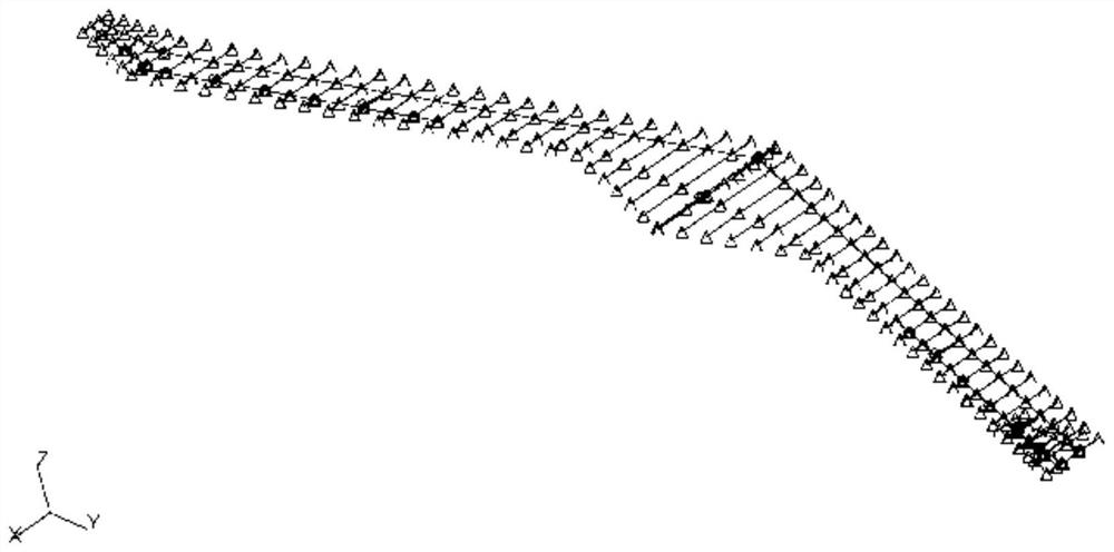
[0102] Using a large aspect ratio flying-wing drone model, the flying-wing drone is mainly composed of a central wing body fusion body and wings on both sides. The wing tip is a swept vertical tail with the same structure as the wing. There are two control surfaces on the trailing edge of each wing, which can control elevators, ailerons and flaps through differential / linkage between different control surfaces. Finite element models such as image 3 shown. The stiffness characteristics of the surface structure are simulated by a finite element elastic beam located at 35.8% of the chord length of the outer wing, and the mass characteristic distribution is simulated by several lumped mass elements located on the wing surface. The wingtip vertical tail also adopts the same structural unit form. Some parameters of the model are shown in Table 1. The process of building a large flexible aircraft structure model is as follows: figure 2 shown.

[0103] Table 1 Parameters of the...


PUM


Abstract

The invention discloses a nonlinear substructure method suitable for the modeling of complex large flexible aircraft. The large flexible aircraft model is divided into wing parts and fuselage parts (including tail wings, etc.); First-order model for modeling: the nonlinear stiffness coefficient is used to construct the dynamic equation of the large deformation structure, and the test load is constructed by multiplying the modal combination by the proportional coefficient. On this basis, the regression analysis of the input test load and its corresponding structural deformation is used. The nonlinear stiffness coefficient is solved by the method to form a nonlinear structural reduced-order model; the fuselage components are modeled by linear mode. The fixed interface modal synthesis method is applied to the wing components to solve the constrained modes, and the free interface modal synthesis method is applied to the fuselage components to solve the remaining modes, and then the structural dynamics equations are formed through the interface displacement and force coordination conditions synthesis set. The method of the invention greatly reduces the cost of modeling and improves the efficiency of modeling and structural analysis.

Description

technical field [0001] The invention belongs to the technical field of structural dynamics and aeroelasticity analysis of aircraft, and in particular relates to a nonlinear substructure method suitable for structural modeling of complex and large flexible aircraft. Background technique [0002] With the rapid development of computer, electronics, materials and control technologies, the scope of application of aeronautical aircraft continues to expand, and the requirements for flight performance continue to increase, followed by an urgent need for new design ideas and analysis methods. Since the 1990s, large flexible aircraft represented by high-altitude long-endurance UAVs and flying-wing UAVs have gradually become the research focus of various aviation powers. This type of aircraft can continuously perform tasks such as military reconnaissance, civil scientific exploration, communication relay and other tasks in a flexible way. Due to its requirements for flight performanc...

Claims


Application Information

Patent Timeline
Patent Type & Authority Patents(China)
IPC IPC(8): G06F30/23G06F30/15G06F30/17G06F119/14
CPCG06F30/23G06F30/15G06F30/17G06F2119/14
Inventor 安朝孟杨谢长川杨超
Owner BEIHANG UNIV
Learn More