
Light emitting device and manufacturing method thereof

A light-emitting device and a manufacturing method technology, which are applied in semiconductor/solid-state device manufacturing, electrical components, electric solid-state devices, etc., can solve the problems of reduced structural strength of reflective sheets, difficulties in producing light-emitting devices, and increased difficulty in making reflective sheets. Assembly Difficulty, Reduce Shadow or Reliability, Good Reliability Effect

Pending Publication Date: 2021-03-30
INNOLUX CORP
View PDF13 Cites 0 Cited by
  • Summary
  • Abstract
  • Description
  • Claims
  • Application Information

AI Technical Summary

Problems solved by technology

As the size of the light-emitting unit decreases or the number of light-emitting units increases, the difficulty of making the reflective sheet increases, the structural strength of the reflective sheet decreases, and the difficulty of assembling the reflective sheet and the light-emitting unit (such as difficulty in alignment) increases, all of which lead to the production of light-emitting devices. difficulty

Method used


Image

  • Light emitting device and manufacturing method thereof
  • Light emitting device and manufacturing method thereof
  • Light emitting device and manufacturing method thereof

Examples


Embodiment Construction

[0011] The present disclosure can be understood by referring to the following detailed description taken in conjunction with the accompanying drawings. It should be noted that, in order to facilitate readers' understanding and brevity of the drawings, several drawings in this disclosure only depict a part of the electronic device / display device, and specific components in the drawings are not drawn according to actual scale. In addition, the number and size of each component in the figure are only for illustration, and are not intended to limit the scope of the present disclosure. For example, the relative sizes, thicknesses and positions of layers, regions or structures may be reduced or exaggerated for clarity.

[0012] Certain terms will be used throughout the specification and claims that follow this disclosure to refer to particular elements. Those skilled in the art should understand that electronic device manufacturers may refer to the same element by different names. ...


PUM


Abstract

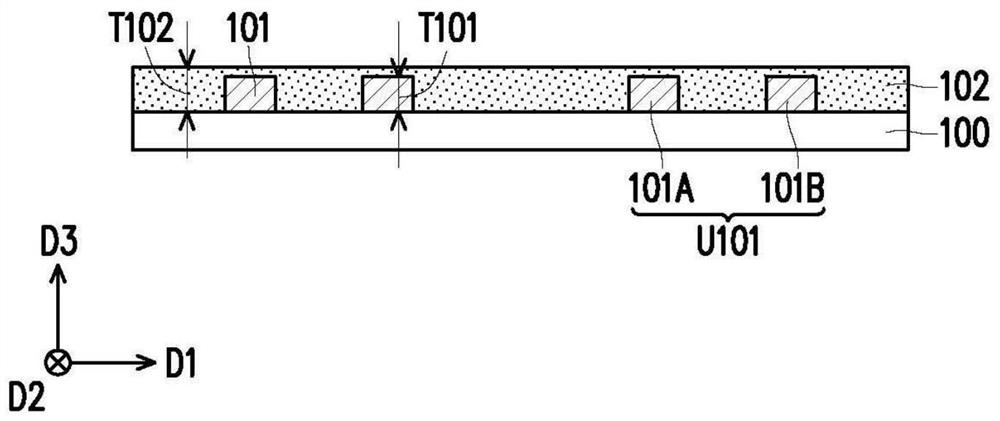
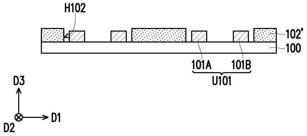
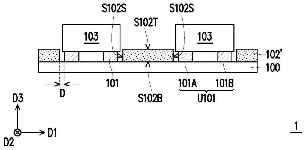
The invention provides a manufacturing method of a light emitting device. The manufacturing method comprises the following steps: providing a driving substrate; disposing a plurality of light emittingunits on the driving substrate; forming a reflective layer on the driving substrate, wherein forming the reflective layer on the driving substrate includes coating the reflective layer on the drivingsubstrate.

Description

technical field [0001] The disclosure relates to an electronic device and a manufacturing method thereof, in particular to a light emitting device and a manufacturing method thereof. Background technique [0002] Traditional light emitting devices use reflective sheets to improve light utilization efficiency, or use reflective sheets to reflect light to illuminate areas where no light emitting units (such as light emitting diodes) are provided. Taking the direct type light-emitting device as an example, openings should be formed in the reflective sheet according to the position, size, or quantity of the light-emitting units, so as to prevent the reflective sheet from covering the light emitting device on the drive substrate after being attached to the drive substrate. unit. As the size of the light-emitting unit decreases or the number of light-emitting units increases, the difficulty of making the reflective sheet increases, the structural strength of the reflective sheet ...

Claims


Application Information

Patent Timeline
IPC IPC(8): H01L33/60H01L51/52H01L25/04H01L25/075H01L51/56
CPCH01L33/60H01L25/0753H01L2933/0058H10K59/90H10K50/856H10K71/00
Inventor 黄维仕卢英瑞杨景仲朱健慈朱明辉林芳禾
Owner INNOLUX CORP
Learn More