Frequency tunable microstrip patch antenna based on half-cut technology

A technology of microstrip patch antenna and microstrip patch, which is applied in the directions of antenna grounding device, antenna grounding switch structure connection, radiation element structure, etc., and can solve the problem that variable capacitance has a great influence on antenna radiation performance, etc.

Active Publication Date: 2021-03-30
NANTONG UNIVERSITY
View PDF8 Cites 0 Cited by
  • Summary
  • Abstract
  • Description
  • Claims
  • Application Information

AI Technical Summary

Problems solved by technology

[0005] However, the above designs all connect the tunable structure directly to the radiation patch, which makes the variable capacitor have a great influence on the radiation performance of the antenna. Therefore, the inventor first proposed a new type of non-contact variable capacitor based on half-cut technology. Loading scheme to design a frequency reconfigurable antenna working in the main mode TM10 mode. Compared with the traditional frequency reconfigurable microstrip patch antenna, the proposed non-contact variable capacitance-loaded antenna based on half-cut technology Achieved a 50% size reduction and separated the radiation patch from the tunable structure, reducing the impact of loading the tunable structure on the antenna radiation performance and improving the design freedom

Method used


Image

  • Frequency tunable microstrip patch antenna based on half-cut technology
  • Frequency tunable microstrip patch antenna based on half-cut technology
  • Frequency tunable microstrip patch antenna based on half-cut technology

Examples


Embodiment Construction

[0018] The present invention will be further described below in conjunction with the accompanying drawings and specific embodiments.

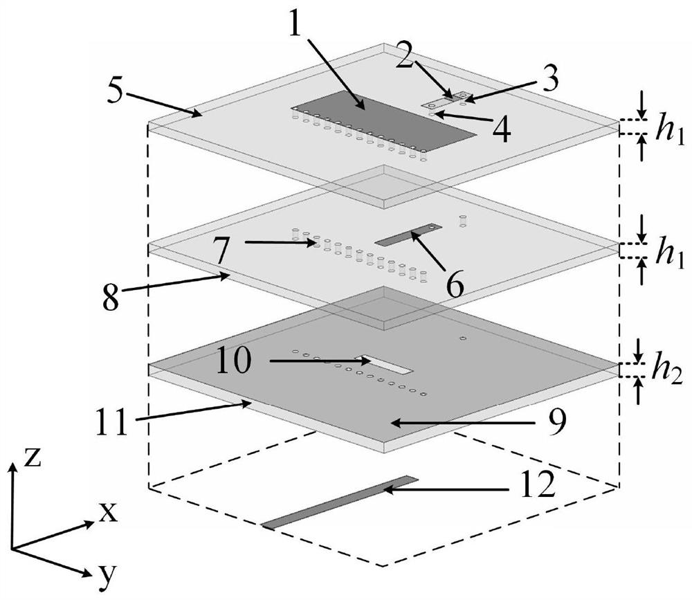
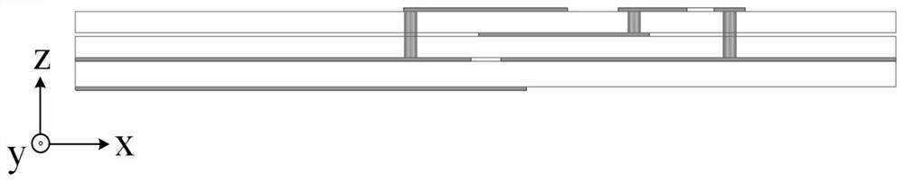
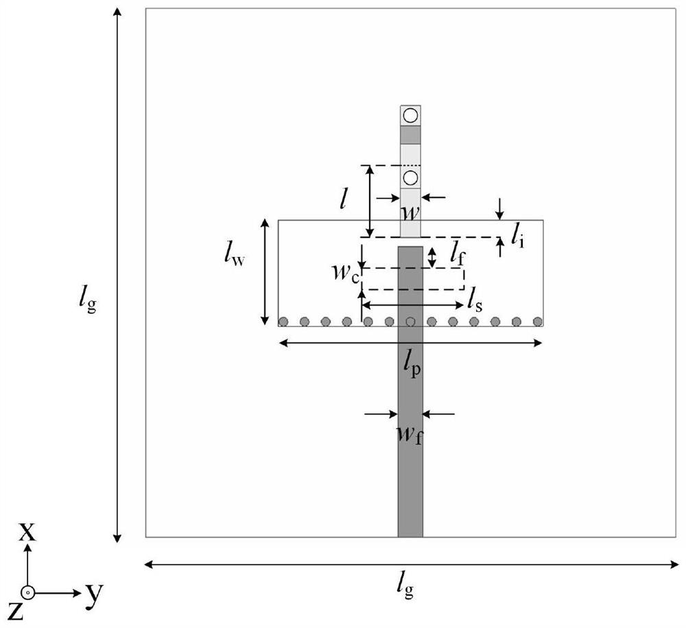
[0019] Such as Figure 1 to Figure 3 As shown, the frequency-tunable microstrip antenna with non-contact variable capacitance loading in this embodiment includes a bottom substrate 11 , a microstrip patch resonator and a microstrip feeder 12 respectively disposed on the upper and lower surfaces of the bottom substrate 11 . The microstrip patch resonator includes a metal reflective floor 9 , an intermediate substrate 8 , a top substrate 5 and a microstrip patch 1 which are sequentially stacked from bottom to top. The microstrip patch 1 is a rectangular microstrip patch, and is disposed in the center of the top substrate 5 . There is a microstrip line 6 for frequency tuning between the top substrate 5 and the middle substrate 8 , and the microstrip line 6 for frequency tuning is arranged along the centerline of the microstrip patch 1 . The micr...


PUM

PropertyMeasurementUnit
dielectric lossaaaaaaaaaa

Abstract

The invention relates to a frequency tunable microstrip patch antenna based on a half-cut technology. Thefrequency tunable microstrip patch antenna comprises a bottom layer substrate, and a microstrippatch resonator and a microstrip feeder which are respectively arranged on the upper surface and the lower surface of the bottom layer substrate, and is characterized in that the microstrip patch resonator comprises a metal reflecting floor, a middle layer substrate, a top layer substrate and a half-cut microstrip patch which are sequentially stacked from bottom to top; a microstrip line for frequency tuning is arranged between the middle-layer substrate and the top-layer substrate; the microstrip line for frequency tuning is overlapped with the microstrip patch in a non-contact manner acrossthe top-layer substrate; the outer end of the microstrip line for frequency tuning is connected with a variable capacitor loaded on the upper surface of the top-layer substrate; one side, far away from the variable capacitor, of the microstrip patch is grounded; and the microstrip line for frequency tuning and the variable capacitor form a non-contact frequency tuning structure used for continuously tuning the frequency of the antenna. The invention provides a novel non-contact variable capacitor loading scheme for the first time to design the frequency-reconfigurable microstrip patch antennaworking under a main mode TM10.

Description

technical field [0001] The invention relates to the technical field of wireless communication, in particular to a frequency-tunable microstrip patch antenna based on half-cut technology. Background technique [0002] With the miniaturization of communication systems, more components need to be integrated into a limited space, so the miniaturization technology of antennas has received extensive attention. But the size of the antenna is closely related to its performance, so the design for miniaturized antenna is not easy. The method of antenna miniaturization can be: (1) Maintain the original frequency of the antenna and reduce its physical size. (2) Keep the physical size of the antenna unchanged and reduce its operating frequency to achieve the effect of reducing the electrical size of the antenna. The miniaturization technology for microstrip antennas is currently mainly based on the use of new materials or novel antenna structures. For example, a compact magnetodielect...

Claims


Application Information

Patent Timeline
Patent Type & Authority Applications(China)
IPC IPC(8): H01Q1/38H01Q1/48H01Q1/50
CPCH01Q1/38H01Q1/50H01Q1/48
Inventor 陈建新张小珂唐世昌王雪颖杨玲玲
Owner NANTONG UNIVERSITY
Why Eureka
Try Eureka