New material processing and mixing treatment device

A mixing treatment and mixing device technology, which is applied in the field of new material processing and mixing treatment devices, can solve the problems of inability to separate the reaction liquid in the lower layer, low reaction rate, uneven stirring of the stirring device, etc., so as to improve the primary reaction rate and improve the treatment effect , blending speed for fast effects

Inactive Publication Date: 2021-04-02
王占文
View PDF6 Cites 0 Cited by
  • Summary
  • Abstract
  • Description
  • Claims
  • Application Information

AI Technical Summary

Problems solved by technology

[0004] Aiming at the deficiencies of the prior art, the present invention provides a new material processing and mixing treatment device, which solves the problem that the

Method used


Image

  • New material processing and mixing treatment device
  • New material processing and mixing treatment device
  • New material processing and mixing treatment device

Examples


Embodiment example 1

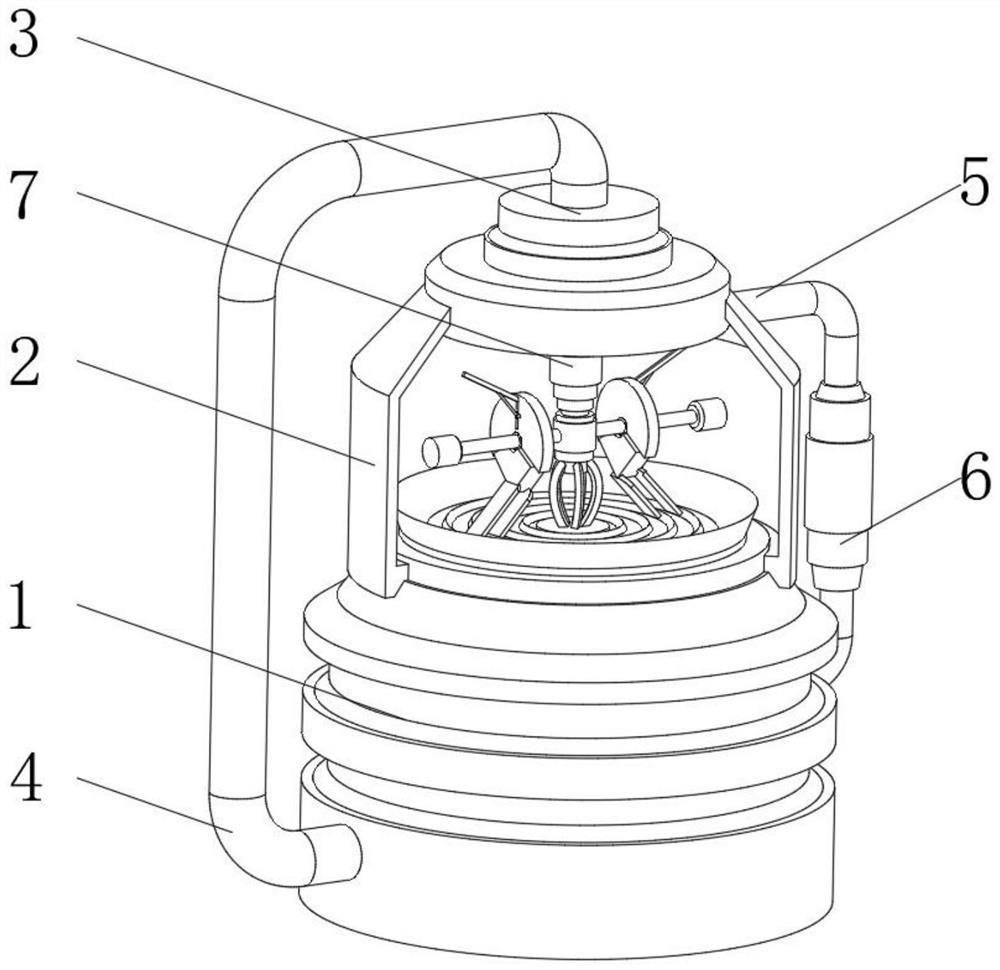
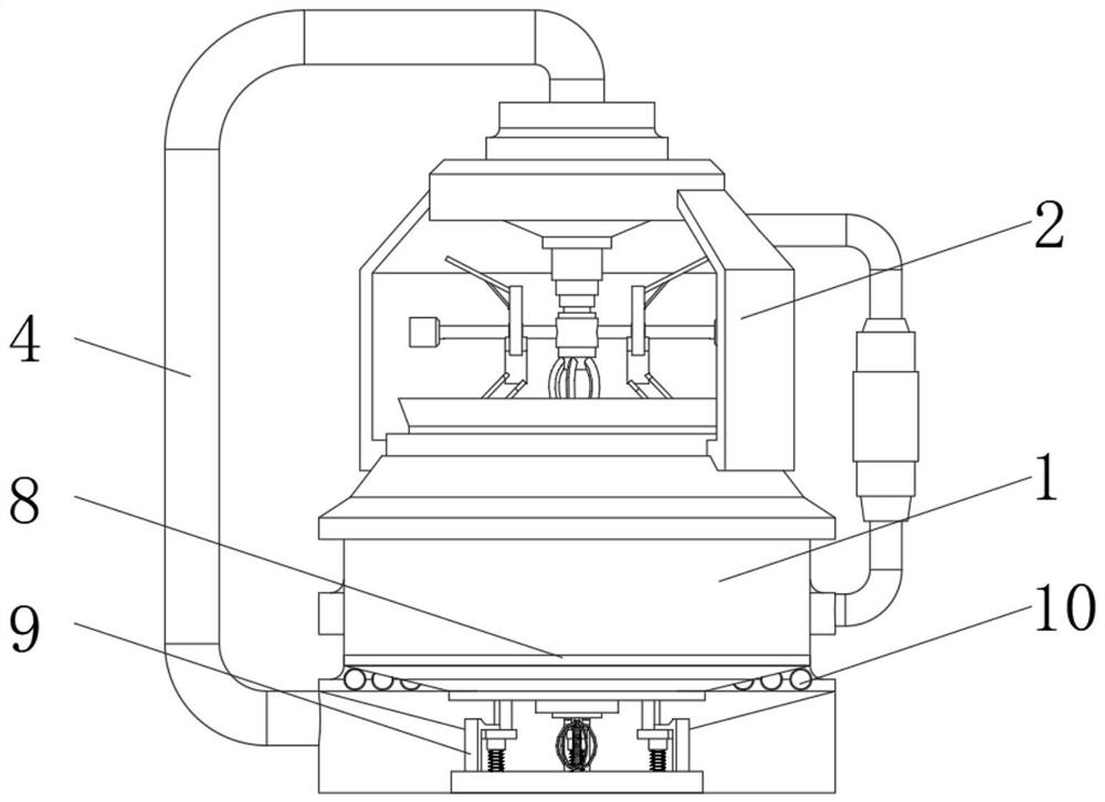
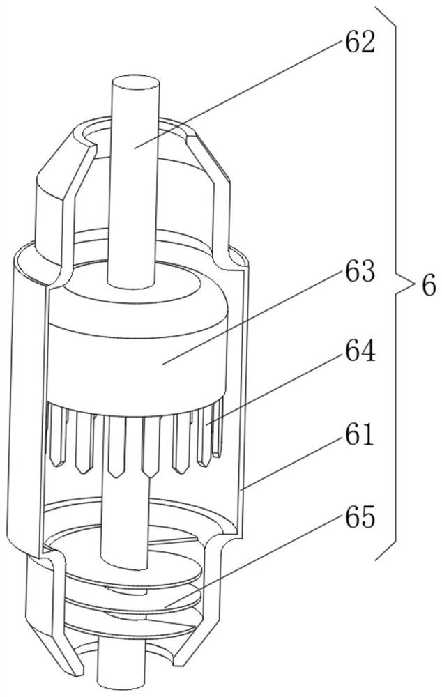
[0033] see Figure 1-4, the present invention provides a technical solution: a new material processing mixing treatment device, including a reaction tank 1 and a mixing treatment tank 2, the top of the mixing treatment tank 2 is provided with a top cover 3, and the top of the top cover 3 is connected to the bottom side of the reaction tank 1 A connection air guide pipe 4 is installed between them, a return air pipe 5 is installed between the top side of the reaction tank 1 and the upper side of the mixing treatment tank 2, a filtering self-generating device 6 is installed in the middle of the return air pipe 5, and a mixing tank 2 is installed inside. Device 7, a reaction chamber is provided inside the reaction tank 1, a pressure trigger device 9 is provided at the bottom of the reaction tank 1, a sedimentation liquid chassis 8 is provided on the inner side of the reaction chamber, and an outer discharge hole 10 is provided on the outer ring side of the reaction tank 1, Outer ...

Embodiment example 2

[0038] see Figure 1-6 , on the basis of the first embodiment, the present invention provides a technical solution: the pressure trigger device 9 includes a support base 91 and an installation top seat 92, an elastic support inner frame 93 is installed between the support base 91 and the installation top seat 92, and supports The base 91 top is provided with a side magnetic frame 94, and the top frame 92 bottom is provided with an upper frame 95, and a supporting spring bar 96 is provided between the upper frame 95 bottom and the supporting base 91, and the upper frame 95 is positioned at the side magnetic frame 94 below.

[0039] Both the side magnetic frame 94 and the upper frame 95 adopt L-shaped frames, and the positions corresponding to the side magnetic frame 94 and the upper frame 95 are set as opposite magnetic poles. After the reactant reacts continuously inside the device, the internal air pressure gradually increases. When the air pressure Greater than the magnetic ...


PUM


Abstract

The invention discloses a new material processing and mixing treatment device. The device comprises a reaction tank and a mixing treatment tank, a top cover is arranged at the top of the mixing treatment tank, a connecting air guide pipe is installed between the top of the top cover and the bottom edge side of the reaction tank, a backflow air pipe is installed between the top edge side of the reaction tank and the upper edge side of the mixing treatment tank, a filtering self-power-generating device is installed in the middle of the backflow gas pipe, a mixing device is installed in the mixing treatment tank, a reaction cavity is formed in the reaction tank, a pressure triggering device is arranged at the bottom of the reaction tank, a deposition liquid base plate is arranged below the inner side of the reaction cavity in summer, and a discharge hole is formed in the side of the outer ring in the reaction tank. The invention relates to the technical field of new material processing. The new material processing and mixing treatment device solves the problems that: a stirring device is often uneven in stirring, existing treatment devices cannot rapidly separate lower-layer reactionliquid, and the internal reaction rate is low.

Description

technical field [0001] The invention relates to the technical field of new material processing, in particular to a new material processing mixing treatment device. Background technique [0002] New materials refer to newly developed or developing structural materials with excellent properties and functional materials with special properties. Structural materials mainly utilize their mechanical properties such as strength, toughness, hardness, and elasticity. Such as new ceramic materials, amorphous alloys (metallic glass), etc. Functional materials mainly use their functions and physical effects such as electricity, light, sound, magnetism, and heat. In recent years, new materials researched and developed in the world mainly include new metal materials, fine ceramics and optical fibers. New materials refer to some materials that are newly developed or under research and development, and have superior performance, which have better performance than traditional materials. ...

Claims


Application Information

Patent Timeline
IPC IPC(8): B01J19/18F01D15/10B03C5/02
CPCB01J19/18F01D15/10B03C5/02
Inventor 王占文
Owner 王占文
Why Eureka
Try Eureka