Continuous and efficient separation equipment for cell engineering

A technology of cell engineering and separation equipment, applied in the field of cell separation, can solve the problems of medical staff not being able to improve their work efficiency, taking up time, and putting samples into centrifuge devices, etc.

Active Publication Date: 2021-04-02
HUNAN KANGRUN PHARMA
View PDF8 Cites 0 Cited by
  • Summary
  • Abstract
  • Description
  • Claims
  • Application Information

AI Technical Summary

Problems solved by technology

[0004] The purpose of the present invention is to provide a continuous and high-efficiency separation device for cell engineering, to solve the problem that the traditional centrifuges in the prior art proposed in the above-mentioned background technology usually require staff to put in and take them out one by one, which takes up precious medical staff. Time, especially during the outbreak, requires more efficiency for the blood testing of patients, and when the medical staff centrifuges the samples, they cannot put the prepared samples into the centrifuge device in large quantities, and let the device automatically process these samples. The samples are automatically installed in the centrifuge device, and the centrifuged samples cannot be automatically transported out of the device after the centrifugation is completed, and the next batch of samples is automatically loaded into the centrifuge device, so that the work efficiency of medical staff cannot be improved. The problem of increasing the burden on medical staff

Method used


Image

  • Continuous and efficient separation equipment for cell engineering
  • Continuous and efficient separation equipment for cell engineering
  • Continuous and efficient separation equipment for cell engineering

Examples


Embodiment Construction

[0033] The following will clearly and completely describe the technical solutions in the embodiments of the present invention with reference to the accompanying drawings in the embodiments of the present invention. Obviously, the described embodiments are only some, not all, embodiments of the present invention. Based on the embodiments of the present invention, all other embodiments obtained by persons of ordinary skill in the art without creative efforts fall within the protection scope of the present invention.

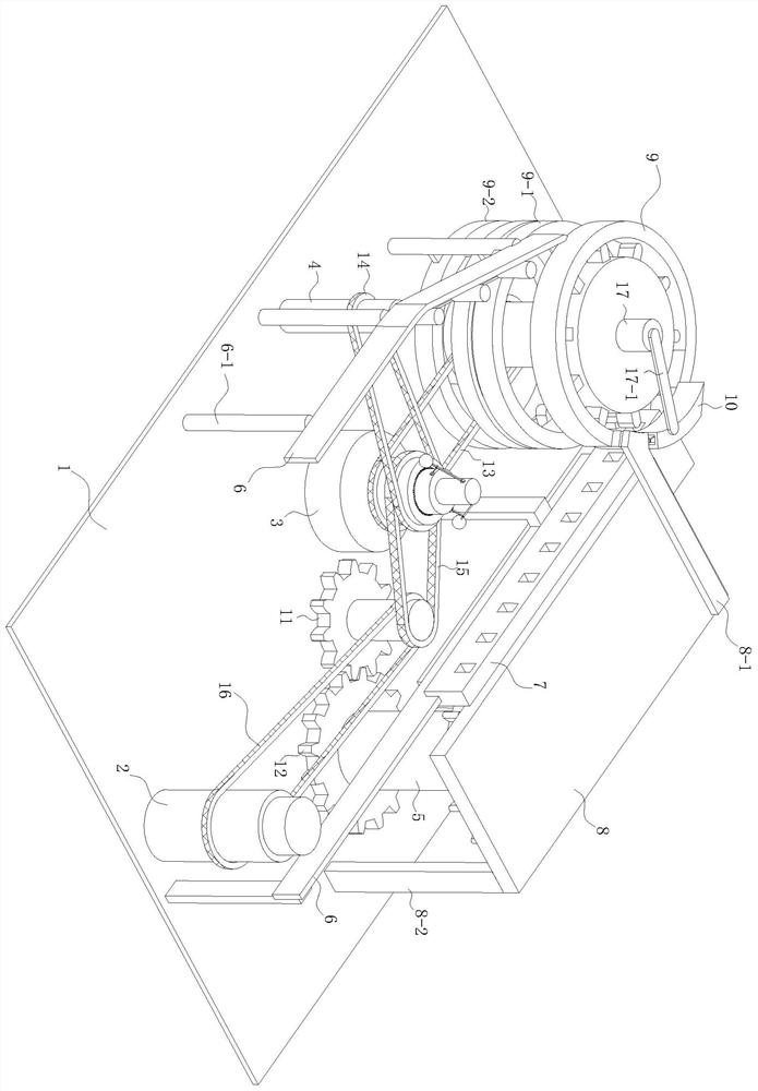
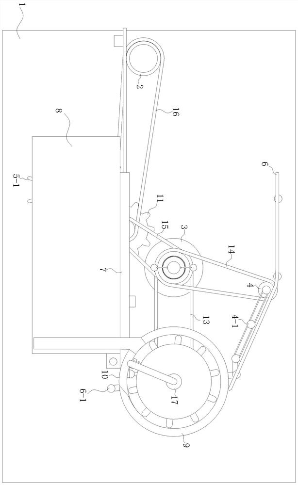
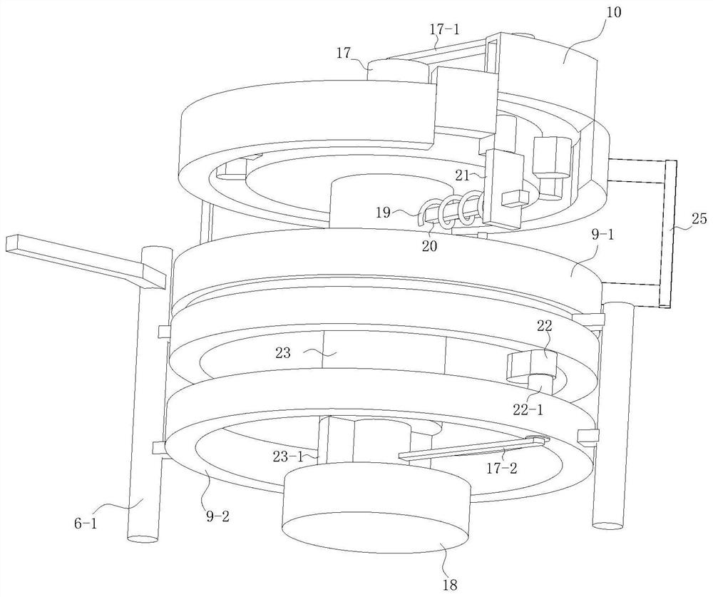
[0034] see Figure 1-9 , the present invention provides a technical solution: a continuous and high-efficiency separation device for cell engineering, including a base plate 1 support device, a transmission mechanism, a power system, a centrifugal mechanism and a discharge mechanism, the support device is arranged on the base plate 1, and the transmission mechanism There is a guide rail 6 installed on the support device, and the load can be installed above the guid...


PUM


Abstract

The invention discloses continuous and efficient separation equipment for cell engineering, and relates to the field of cell centrifugation. The equipment comprises a conveying mechanism, a centrifugal mechanism, a discharging mechanism and a power system; the power system is connected with the conveying mechanism, the discharging mechanism and the centrifugal mechanism through belts; the conveying mechanism is fixedly connected to a bottom plate through a supporting device; the tail end of the conveying mechanism is connected with the centrifugal mechanism; a first circular ring is arranged above the centrifugal mechanism and provided with a notch allowing an object carrying chain to enter; the discharging mechanism is arranged on the other side of the first circular ring; and a guide rail in the discharging mechanism is tangent to the first circular ring. The equipment solves the problems that a cell centrifugal device cannot conduct large-batch centrifugation at a time and manual supervision is needed in the prior art.

Description

technical field [0001] The invention relates to the field of cell separation, in particular to a continuous and efficient separation device for cell engineering. Background technique [0002] Traditional centrifuges in the prior art usually require staff to put in and take them out one by one, and putting multiple samples into the centrifuge at the same time will cause the operator to be unable to accurately insert the test tube into the centrifuge due to the obstruction of the line of sight. In the process of putting in and taking out the samples in the centrifuge, it is necessary to complete the action of opening and closing the centrifuge. The operation is very cumbersome and inefficient. Detection requires efficiency, and when the medical staff centrifuges the samples, they cannot put the prepared samples into the centrifuge device in large quantities, and let the device automatically install the samples in the centrifuge device, let alone in the centrifuge. After the c...

Claims


Application Information

Patent Timeline
Patent Type & Authority Applications(China)
IPC IPC(8): B04B11/02
CPCB04B11/02
Inventor 师维
Owner HUNAN KANGRUN PHARMA
Why Eureka
Try Eureka