Movable type seal splicing assembly

A seal and movable type technology, which is applied in the field of movable type seal splicing components, can solve the problems of high processing cost, high size and precision requirements, low degree of freedom, etc., and achieve the effect of reducing production costs

Pending Publication Date: 2021-04-02
曲阜市天成电子商务有限公司
View PDF0 Cites 0 Cited by
  • Summary
  • Abstract
  • Description
  • Claims
  • Application Information

AI Technical Summary

Problems solved by technology

The mortise and tenon structure and the magnetic adsorption structure have high requirements on the size and precision of the characters and seal carriers. They must be assembled and spliced ​​according to a fixed position. After the assembly, the printed ones are all in a certain order, and the degree of freedom is too low.
Moreover, at present, the characters are made of metal, and the processing cost is high, and the surface of the material is high when stamping, and if there is a slight unevenness, some strokes will not be printed.

Method used


Image

  • Movable type seal splicing assembly

Examples


Embodiment 1

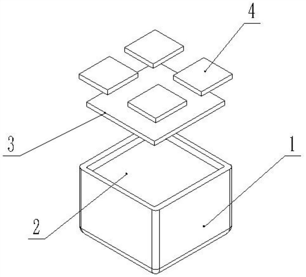
[0019] see figure 1 , in the embodiment of the present invention, a movable type seal splicing assembly includes a seal shell 1, a sticker 3 and stamp characters 4, and a groove is provided on the side of the seal shell 1 close to the sticker 3, so that The self-adhesive 3 is adhered in the groove, and the length and width of the self-adhesive 3 are adapted to the size of the stamp groove 2, so that when the self-adhesive 3 is adhered to the stamp groove 2, it is not necessary to The dry glue 3 will not move in the stamp groove 2, and the stamp characters 4 are set on the side of the sticker 3 away from the stamp groove 2. The stamp characters 4 can be prepared in advance according to the needs of multiple groups of different types of characters or pattern, stick the stamp characters 4 on the sticker 3 according to a certain arrangement, and then dip the stamp characters 4 with inkpad to complete the function of the stamp.

[0020] see figure 1 , the seal character 4 and the...

Embodiment 2

[0024] see figure 1 , in the embodiment of the present invention, the seal groove 2 can be made of wood or metal, and different materials can be selected according to personal preferences and actual needs. It is circular or other shapes, and according to the shape of the actual required stamp, the shapes of the stamp housing 1, the stamp groove 2 and the stamp characters 4 are determined. One side of the stamp characters 4 is engraved with patterns or words, and in addition One side is flat to facilitate adhesion with the self-adhesive 3.

[0025] see figure 1 , the seal character 4 is adhered to the sticker 3 through the sticker 3 when in use, while ensuring the same stamping effect, there is no need for an overly precise combination structure, which can greatly reduce the production of movable type combined seals cost.

[0026] see figure 1 , when the sticker 3 and the stamp characters are in use, you can also stick the sticker 3 to the bottom of the rest of the stamps, ...


PUM


Abstract

The invention discloses a movable type seal splicing assembly which comprises a seal shell, non-setting adhesive and seal character particles. A seal groove is formed in the bottom of the seal shell,the depth of the seal groove is larger than the thickness of the non-setting adhesive, the non-setting adhesive is movably connected with the seal groove, and the seal character particles are movablyconnected with the non-setting adhesive. Through the structure of the non-setting adhesive and the seal character particles, the problem that common movable type seals must arrange characters in a fixed sequence is solved, and free arrangement and combination according to the own needs are achieved; the seal character particles solve the problem that metal character particles are prone to being stamped out during stamping, and while the same stamping effect is guaranteed, an over-precise combined structure is not needed, so that the production cost of the movable type combined seal is greatlyreduced.

Description

technical field [0001] The invention relates to the technical field of seals, in particular to a movable type seal splicing assembly. Background technique [0002] Seals, also known as stamps, are used as stationery printed on documents to indicate identification or signature. Generally, stamps are first stained with paint and then printed. Those without paint and printed on a flat surface will appear concave and convex. They are called steel seals. Some are printed on A wax seal on wax or wax, on an envelope. The production materials are metal, wood, stone, jade and so on. [0003] The traditional seal engraving needs to receive the customer's name and then typesetting and engraving. The general processing time is about 10 minutes, and professional processing equipment is required. Currently, the movable type seals on the market are made of lead type and copper type. The link structure is Magnetic attraction and mortise and tenon structure splicing. The mortise and tenon...

Claims


Application Information

Patent Timeline
IPC IPC(8): B41K1/08B41K1/36
CPCB41K1/08B41K1/36
Inventor 张志伟
Owner 曲阜市天成电子商务有限公司
Why Eureka
Try Eureka