Enhanced heat transfer type solar flat plate collector

A technology of solar panels and enhanced heat transfer, which is applied to solar collectors, solar collector safety, solar collector heat insulation, etc., can solve problems such as inability to transmit solar energy, reduce dirt deposition, and improve heat transfer efficiency , the effect of increasing the heat transfer rate

Active Publication Date: 2021-04-02
ZHENGZHOU UNIVERSITY OF LIGHT INDUSTRY
View PDF7 Cites 0 Cited by
  • Summary
  • Abstract
  • Description
  • Claims
  • Application Information

AI Technical Summary

Problems solved by technology

[0006] The present invention aims to solve the problem that the heat absorber of the existing flat-plate solar heat collector cannot efficiently transmit solar energy to the working medium in the flow channel

Method used


Image

  • Enhanced heat transfer type solar flat plate collector
  • Enhanced heat transfer type solar flat plate collector
  • Enhanced heat transfer type solar flat plate collector

Examples


specific Embodiment approach 1

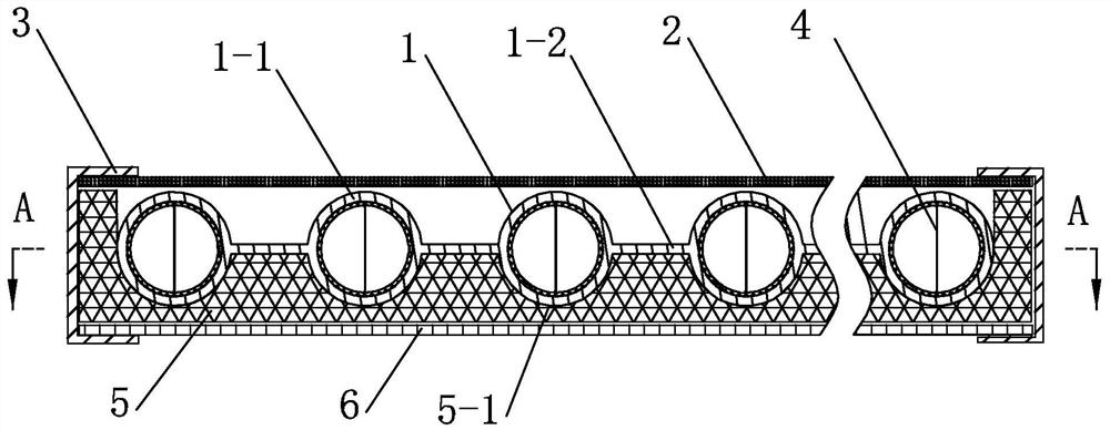
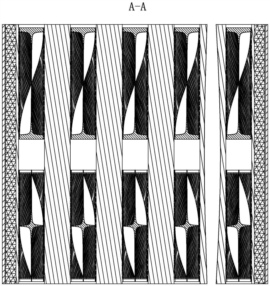
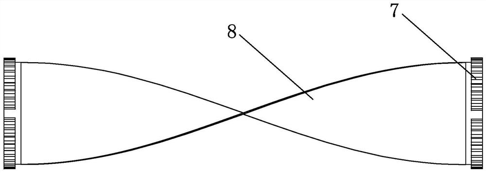
[0014] Specific implementation mode one: combine Figure 1 to Figure 15 Describe this embodiment, a heat transfer-enhanced solar flat panel heat collector of this embodiment, which includes a heat absorber 1, a transparent cover plate 2, a frame 3, at least one spoiler 4, thermal insulation material 5 and a back plate 6 , the heat absorber 1 includes multiple sets of circular tubes 1-1 and multiple heat absorbing plates 1-2, multiple sets of circular tubes 1-1 are arranged in parallel, and a heat absorbing plate passes between two adjacent sets of circular tubes 1-1 1-2 connection; the thermal insulation material 5 is installed on the back plate 6, the heat absorber 1 is installed on the thermal insulation material 5, and at least one spoiler 4 is installed in each group of round tubes 1-1, and the same group of round tubes 1 The rotation direction of the two adjacent spoilers 4 in -1 is opposite. On the cover plate 2 and the back plate 6; each turbulence device 4 includes tw...

specific Embodiment approach 2

[0017] Specific implementation mode two: combination figure 1 To illustrate this embodiment, a plurality of arc-shaped grooves 5-1 are equally spaced on the upper end surface of the thermal insulation material 5 of this embodiment. With such arrangement, it is convenient to embed multiple sets of circular tubes 1-1 into the arc-shaped grooves 5-1, and the heat-absorbing plate 1-2 can be placed between two connected arc-shaped grooves 5-1. Other compositions and connections are the same as in the first embodiment.

specific Embodiment approach 3

[0018] Specific implementation mode three: combination figure 1 and Figure 4 The present embodiment will be described. The chainring 7 of this embodiment is an annular chainring with notches. Such setting prevents its endothermic expansion from extruding the circular tube flow path. Other compositions and connections are the same as those in Embodiment 1 or Embodiment 2.


PUM


Abstract

The invention discloses an enhanced heat transfer type solar flat plate collector, and relates to a solar flat plate collector. The enhanced heat transfer type solar flat plate collector solves the problem that an existing flat plate type solar heat collector heat absorption body cannot efficiently transmit solar energy to a working medium in a flow channel. The enhanced heat transfer type solar flat plate collector is characterized in that a plurality of groups of circular tubes are arranged in parallel, and every two adjacent groups of circular tubes are connected through a heat absorbing plate; a heat preservation material is installed on a back plate, a heat absorption body is installed on the heat preservation material, one turbulent flow device is installed in each group of circulartubes, the two sides of the heat preservation material are higher than the upper surface of the heat absorption body, a transparent cover plate covers the heat preservation material, and a frame is installed on the transparent cover plate and the back plate; and each turbulent flow device comprises two fluted discs, at least one torsion plate and a plurality of adherent turbulence strips, the twofluted discs are oppositely arranged, the middle parts of the two fluted discs are connected through the at least one torsion plate, and the adherent turbulence strips with the rotating direction opposite to that of the torsion plate are uniformly distributed in the circumferential directions of the two fluted discs. The enhanced heat transfer type solar flat plate collector is used for solar heatcollection.

Description

technical field [0001] The invention relates to a flat plate heat collector, in particular to an enhanced heat transfer type solar plate heat collector. Background technique [0002] In recent years, with the increasingly severe environmental pollution problems, solar energy, as a clean energy source, has been paid more and more attention by scientific and technological workers. The flat panel solar collector is a basic component for converting solar energy into heat energy. It is mainly composed of a frame, a transparent cover, a heat absorber, an insulation material, a back plate and a seal. Cross-sectional metal runners for the passage of heat-conducting media. Flat-plate solar collectors have the advantages of simple structure, less maintenance and failure, convenient installation, and low cost. At present, they have been widely used in many fields such as domestic water heating, building heating and air conditioning, refrigeration and heating. [0003] However, there ...

Claims


Application Information

Patent Timeline
IPC IPC(8): F24S10/50F24S40/20F24S80/30F24S80/60
CPCF24S10/50F24S80/60F24S80/30F24S40/20Y02E10/44
Inventor 王宏韩晨谷永杰王浩鹏遆曙光杨存祥李森李金凤
Owner ZHENGZHOU UNIVERSITY OF LIGHT INDUSTRY
Why Eureka
Try Eureka