
High-speed railway foundation bed slurry-turning mud-emitting fine particle migration detection device

A technology of mud-flushing and detection devices, which is applied in the direction of measuring devices, particle and settlement analysis, soil material testing, etc., can solve the problems of insufficient value height, mud-flushing and mud-flushing that cannot provide accurate and reliable theoretical support, and achieve the effect of accurate results

Active Publication Date: 2021-04-02
SHANDONG UNIV
View PDF5 Cites 0 Cited by
  • Summary
  • Abstract
  • Description
  • Claims
  • Application Information

AI Technical Summary

Problems solved by technology

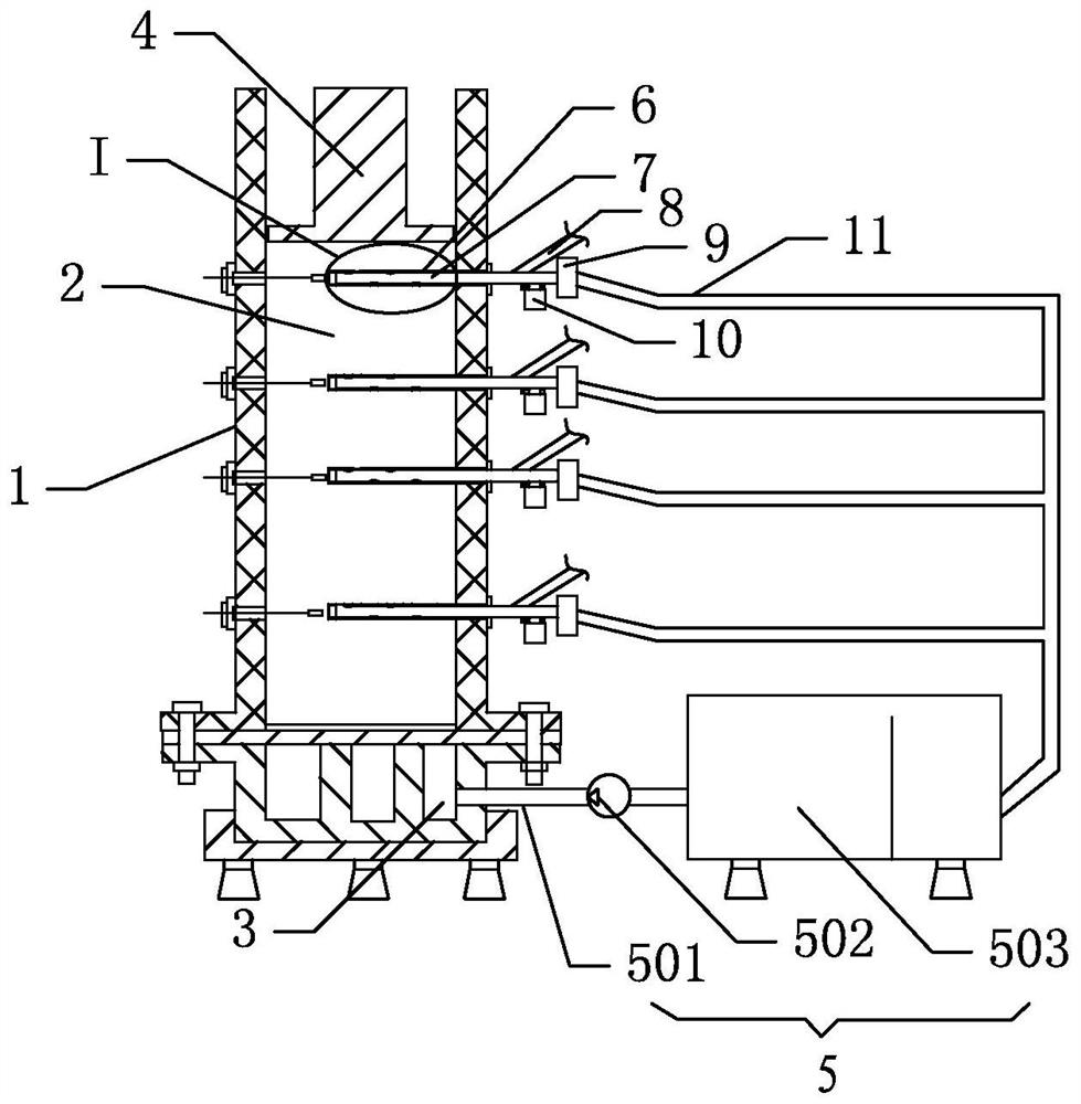
[0004] This application is to solve the existing high-speed railway subgrade tests on mud-flushing diseases, which are mainly completed by using one-dimensional seepage experiments, so that the migration rules of mud-flushing fine particles obtained in existing tests can be used as a reference. The value is not high enough , which leads to the problem that accurate and reliable theoretical support cannot be provided in terms of the formation, evolution and impact on the project. This application designs a detection device for fine particle migration of high-speed railway subgrade mud. The specific scheme adopted is :

Method used


Image

  • High-speed railway foundation bed slurry-turning mud-emitting fine particle migration detection device
  • High-speed railway foundation bed slurry-turning mud-emitting fine particle migration detection device
  • High-speed railway foundation bed slurry-turning mud-emitting fine particle migration detection device

Examples


Embodiment Construction

[0032] In order to clearly illustrate the technical features of this solution, the present invention will be described in detail below through specific implementation methods and in conjunction with the accompanying drawings.

[0033] In addition, in the description of the present invention, it should be understood that the terms "center", "upper", "lower", "front", "rear", "left", "right", "vertical", "horizontal" ", "Top", "Bottom", "Inner", "Outer", "Axial", "Radial", "Circumferential" and other indicated orientations or positional relationships are based on the orientations or positional relationships shown in the drawings , is only for the convenience of describing the present invention and simplifying the description, but does not indicate or imply that the referred device or element must have a specific orientation, be constructed and operated in a specific orientation, and thus should not be construed as limiting the present invention.

[0034] Such as Figure 1-6 As ...


PUM


Abstract

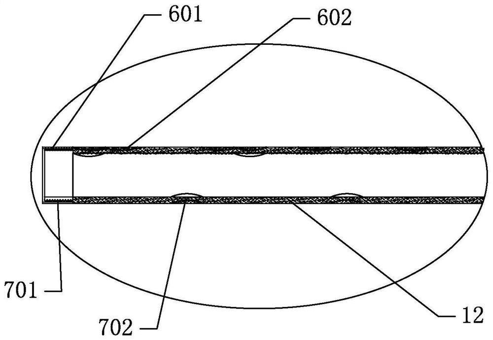
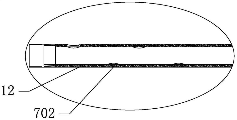
The invention relates to a high-speed railway foundation bed slurry-turning mud-emitting fine particle migration detection device, and belongs to the field of railway slurry-turning mud-emitting detection. The device comprises a sample model box provided with a sample filling cavity, and a liquid inlet is formed in the bottom, corresponding to the sample filling cavity, of the sample model box; the loading mechanism is used for loading an impact load into the sample filling cavity; the water supply system feeds liquid into the sample filling cavity in the vertical direction through the liquidinlet; the plurality of collecting guide pipe are arranged at intervals along the vertical direction, each collecting guide pipe is horizontally arranged, and each collecting guide pipe is provided with a plurality of collecting holes at intervals along the horizontal direction; a reversing switch assembly is arranged on the collecting guide pipe and used for opening and closing the collecting holes, so that only one of the collecting holes in different positions is conducted; and according to the scheme, not only can the migration situation of the slurry-turning mud in the vertical directionbe detected, but also the migration situation of the slurry-turning mud in the transverse direction can be detected, and the influence of the boundary on the slurry-turning mud in the test process canbe reflected from the side face, so it is guaranteed that the migration result of fine particles of the slurry-turning mud in the test is relatively accurate.

Description

technical field [0001] The invention relates to the field of detection of mud and turbidity of railways, in particular to a device for detecting migration of fine particles of mud and turbidity of high-speed railway subgrade beds. Background technique [0002] The subgrade is an important part of the railway line, and its function is to bear the dynamic load of the train and the load of the superstructure. Slurry and oozing of subgrade bed is a new type of disease of railway track, which has an important impact on the safety and comfort of line operation. Occurrence of the phenomenon of slurry and mud discharge may not only cause uneven subsidence of the subgrade, affect the normal operation of the train, increase the maintenance cost of the line, but may also pose a great safety hazard to the operation of the train in severe cases. [0003] The current research on mud and mud pumping of railways relies on on-site surveys and indoor model tests. The existing indoor simulati...

Claims


Application Information

Patent Timeline
Patent Type & Authority Applications(China)
IPC IPC(8): G01N15/00G01N33/24
CPCG01N15/00G01N33/24G01N2015/0061
Inventor 蒋红光李宜欣迟浩然姚凯梁明张吉哲齐辉姚占勇
Owner SHANDONG UNIV
Learn More