
Radar monitoring device for unmanned edge cooperation

A technology of unmanned driving and monitoring devices, which is applied in measuring devices, radio wave measuring systems, and utilizing re-radiation. Damage, the effect of improving the reliability of use

Pending Publication Date: 2021-04-02
江苏云工场信息技术有限公司
View PDF0 Cites 0 Cited by
  • Summary
  • Abstract
  • Description
  • Claims
  • Application Information

AI Technical Summary

Problems solved by technology

[0002] As we all know, the radar monitoring device for unmanned driving edge collaboration is an auxiliary device used on unmanned vehicles to monitor the surrounding conditions during the driving process of unmanned vehicles. It has been widely used in the field of unmanned driving. The existing unmanned driving edge collaborative radar monitoring device includes a car body, a fixing seat, a mounting column and a radar body, the bottom of the fixing seat is connected to the top of the car body, the top of the mounting column is connected to the bottom of the radar body, and the mounting column is connected to the bottom of the radar body. The bottom end is connected to the central area of ​​the top of the fixed seat; when the existing unmanned driving edge cooperative radar monitoring device is used, the surrounding conditions during the driving process of the car body can be monitored through the radar body; an existing unmanned driving edge During the use of the cooperative radar monitoring device, it was found that when the car body is in a stopped state, the radar body does not work at this time. In rainy and snowy weather, the radar body is directly exposed to rain and snow, which is easy to shorten, and the service life of the radar body , leading to poor reliability in use; the horizontal angle of the radar body is fixed, and it is not convenient to adjust according to needs, resulting in high limitations in its use

Method used


Image

  • Radar monitoring device for unmanned edge cooperation
  • Radar monitoring device for unmanned edge cooperation
  • Radar monitoring device for unmanned edge cooperation

Examples


Embodiment Construction

[0018] The specific implementation manners of the present invention will be further described in detail below in conjunction with the accompanying drawings and embodiments. The following examples are used to illustrate the present invention, but are not intended to limit the scope of the present invention.

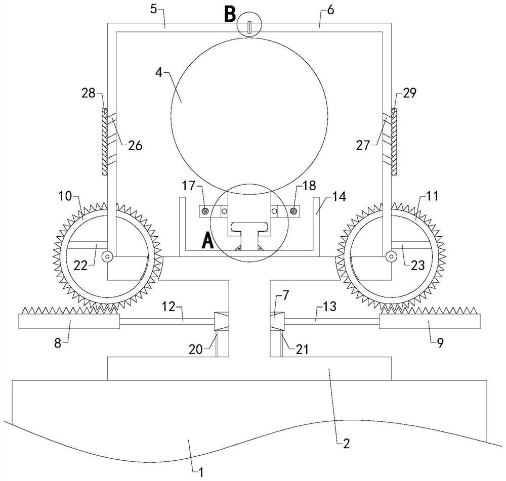
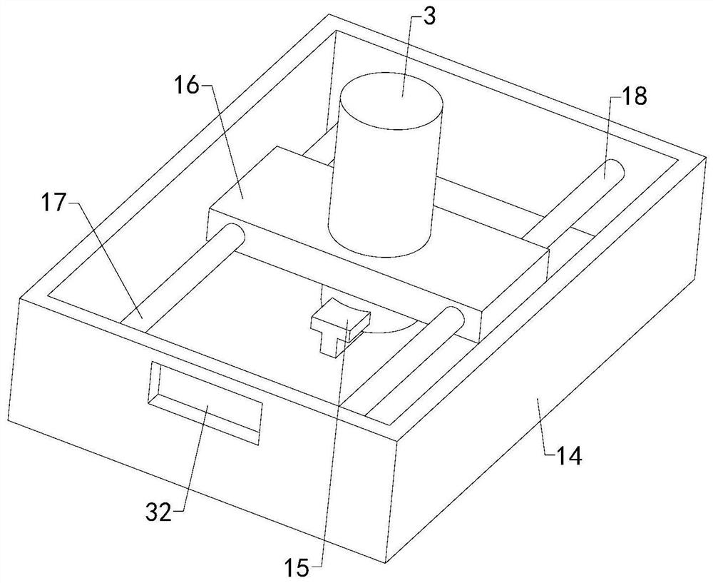
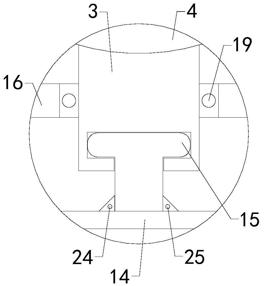
[0019] Such as Figure 1 to Figure 4 As shown, a radar monitoring device for unmanned driving edge collaboration of the present invention includes a car body 1, a fixing seat 2, a mounting column 3 and a radar body 4, the bottom of the fixing seat 2 is connected to the top of the car body 1, and the mounting column 3 The top is connected with the bottom end of the radar body 4; it also includes a left housing 5, a right housing 6, a double-headed cylinder 7, a left rack 8 and a right rack 9, and the inside of the left housing 5 and the right housing 6 are respectively provided with left Inner cavity and right inner cavity, left housing 5 and right housing 6 bottom ends ar...


PUM


Abstract

The invention relates to the technical field of unmanned auxiliary devices, in particular to a radar monitoring device for unmanned edge cooperation, which can protect a radar body when a vehicle bodyis in a stop state, reduce damage of rain and snow to the radar body and prolong the service life of the radar body. The angle of the radar body can be adjusted; the device comprises the vehicle body, a fixing seat, a mounting column and the radar body. The device further comprises a left shell, a right shell, a double-head air cylinder, a left rack and a right rack, a left gear ring and a rightgear ring are fixedly arranged at the lower left corner of the left shell and the lower right corner of the right shell respectively, and a left telescopic rod and a right telescopic rod are arrangedat the left output end and the right output end of the double-head air cylinder respectively; the device further comprises a support, a sliding rail, a moving plate, a left guide column and a right guide column, a connecting groove is formed in the top end of the support, a sliding groove is formed in the bottom end of the mounting column, a rotating hole is longitudinally formed in the center area of the top end of the moving plate, the top end of the mounting column penetrates through the rotating hole, and a bearing set is arranged between the top end of the mounting column and the inner side wall of the rotating hole.

Description

technical field [0001] The invention relates to the technical field of unmanned auxiliary devices, in particular to a radar monitoring device for unmanned edge collaboration. Background technique [0002] As we all know, the radar monitoring device for unmanned driving edge collaboration is an auxiliary device used on unmanned vehicles to monitor the surrounding conditions during the driving process of unmanned vehicles. It has been widely used in the field of unmanned driving. The existing unmanned driving edge collaborative radar monitoring device includes a car body, a fixing seat, a mounting column and a radar body, the bottom of the fixing seat is connected to the top of the car body, the top of the mounting column is connected to the bottom of the radar body, and the mounting column is connected to the bottom of the radar body. The bottom end is connected to the central area of ​​the top of the fixed seat; when the existing unmanned driving edge cooperative radar monit...

Claims


Application Information

Patent Timeline
IPC IPC(8): G01S13/931G01S7/02
CPCG01S13/931G01S7/02
Inventor 季黎俊朱永
Owner 江苏云工场信息技术有限公司
Features
  • Generate Ideas
  • Intellectual Property
  • Life Sciences
  • Materials
  • Tech Scout
  • Unparalleled Data Quality
  • Higher Quality Content
  • 60% Fewer Hallucinations
Learn More