
Method for positioning engine valve grabbing point

A technology of engine valve and positioning method, which is applied in image data processing, instrumentation, calculation, etc., can solve problems such as difficult separation of point cloud, incorrect positioning of grabbing points, and lack of quality of point cloud at the top of the valve, so as to ensure accuracy, Guaranteed consistent effect

Active Publication Date: 2021-04-02
聚时科技(江苏)有限公司
View PDF5 Cites 0 Cited by
  • Summary
  • Abstract
  • Description
  • Claims
  • Application Information

AI Technical Summary

Problems solved by technology

[0003] In 3D vision, due to the reflective characteristics of the engine valve itself, the point cloud collected by the camera hardware is often incomplete, especially the top of the valve is not only affected by reflection, but also affected by the imaging characteristics of the 3D camera point cloud. Cloud quality is often severely lacking, which makes it extremely difficult to locate grab points
[0004] The traditional engine valve grab point location often adopts the point cloud European clustering method to segment the valve point cloud, and then performs principal component analysis (Principal Components Analysis, PCA) and other processing on the segmented point cloud to obtain the grab point pose. This method can achieve better results when the parts are placed relatively scattered, but when the parts are placed relatively compactly and the point clouds between the parts are connected together, the point cloud is difficult to separate, and when the point cloud at the top of the valve is incomplete , the calculated position and attitude of the grasping point will have a certain deviation, resulting in incorrect positioning of the grasping point

Method used


Image

  • Method for positioning engine valve grabbing point
  • Method for positioning engine valve grabbing point
  • Method for positioning engine valve grabbing point

Examples


Embodiment

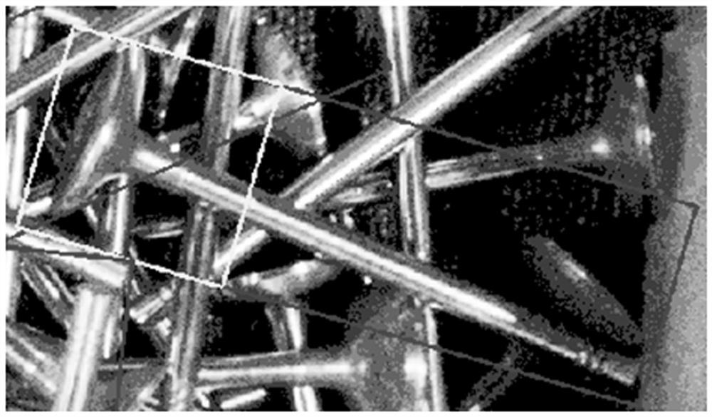
[0038] A 3D camera is used to collect 3D point clouds and 2D images of automobile engine valves, and the 2D images are recognized by a model trained with 600 2D images of automobile engine valves to obtain the overall oblique frame of the automobile engine valve and the top oblique frame of the automobile engine valve (such as image 3 shown), the 3D point cloud is combined with the overall oblique frame of the automobile engine valve to obtain the overall 3D point cloud of the valve through oblique frame filtering (such as Figure 4 shown), using region growing clustering for segmentation, where the smoothness threshold is set to 4°, the segmented car engine valve stem (such as Figure 5 As shown), it can be seen that the stem part of the car engine valve is relatively complete through the segmentation of the region growth cluster, and the 3D point cloud of other interference car engine valves and the 3D point cloud of the top of the car engine valve are segmented.

[0039] T...


PUM


Abstract

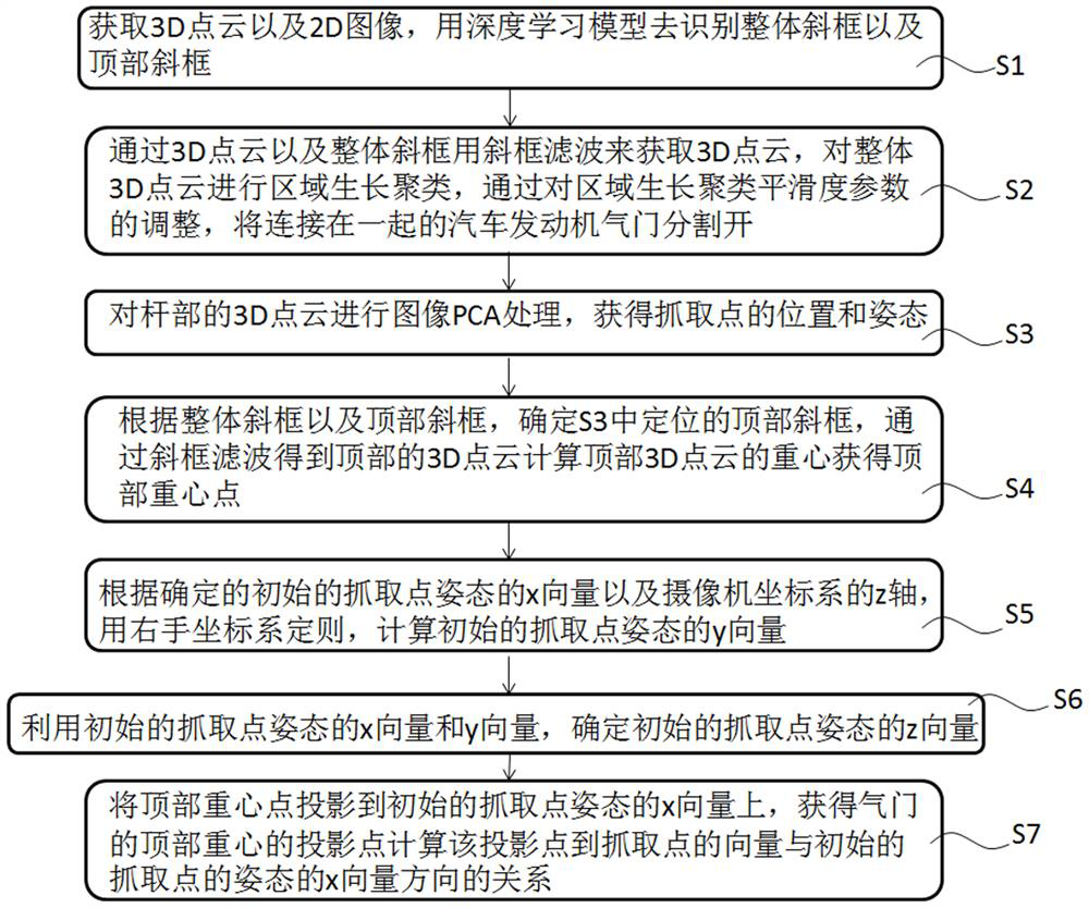
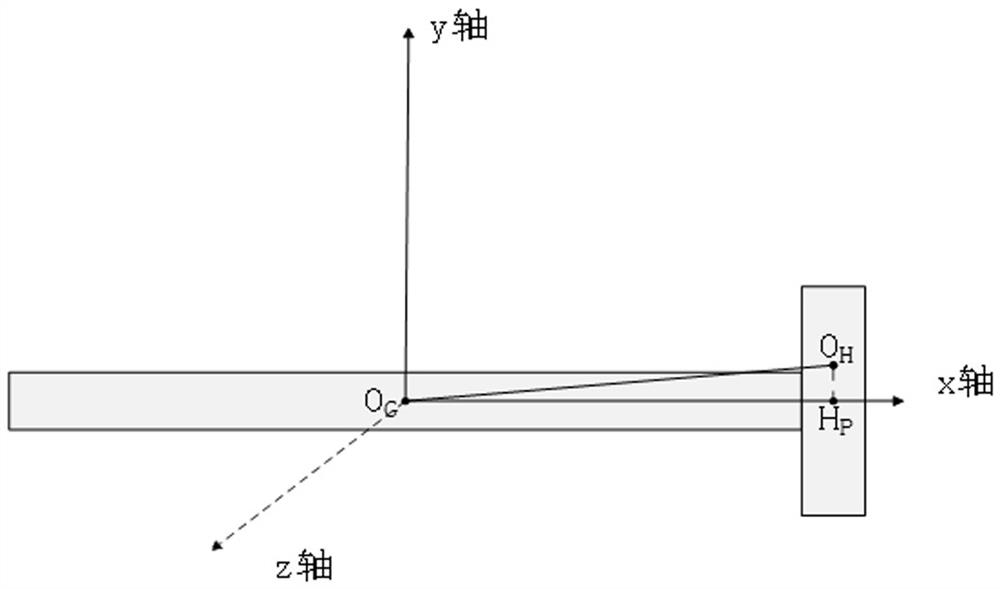
The invention discloses a method for positioning an engine valve grabbing point. The method comprises the following steps: acquiring 3D point cloud and a corresponding 2D image; obtaining the overall3D point cloud through the 3D point cloud and the overall inclined frame by using inclined frame filtering, carrying out region growth clustering on the overall 3D point cloud, and segmenting the automobile engine valve by adjusting the smoothness parameter of the region growth clustering; performing image PCA processing on the 3D point cloud of the rod part to obtain the position and posture of agrabbing point; determining a corresponding top inclined frame according to the overall inclined frame and the top inclined frame, obtaining a top 3D point cloud through inclined frame filtering, calculating the gravity center of the top 3D point cloud, and obtaining the top gravity center point of the automobile engine valve; projecting the obtained top gravity center point to the x vector of the initial grabbing point posture to obtain a projection point of the top gravity center, and determining the direction of the x vector of the initial grabbing point posture; calculating a y vector ofthe initial grabbing point posture according to the x vector and the z axis of the initial grabbing point posture; and determining a z vector of the initial grabbing point posture by utilizing the x vector and the y vector.

Description

technical field [0001] The invention relates to the technical field of grab point positioning, in particular to a method for locating an engine valve grab point. Background technique [0002] With the improvement of industrial automation technology, the development of automobile automation production is getting faster and faster, and the automatic grabbing of automobile engine valve parts is also required. In order to facilitate grabbing, the grabbing point of the engine valve is generally required to be on the valve stem, and the grabbing posture should be consistent with respect to the top of the valve. [0003] In 3D vision, due to the reflective characteristics of the engine valve itself, the point cloud collected by the camera hardware is often incomplete, especially the top of the valve is not only affected by reflection, but also affected by the imaging characteristics of the 3D camera point cloud. Cloud quality is often severely lacking, which makes it extremely dif...

Claims


Application Information

Patent Timeline
Patent Type & Authority Applications(China)
IPC IPC(8): G06T7/73G06T7/11G06T19/20
CPCG06T19/20G06T2207/10028G06T2207/30164G06T2219/2004G06T7/11G06T7/73
Inventor 权稳稳李诗杨庆研
Owner 聚时科技(江苏)有限公司
Learn More