Arc extinguishing system and contactor

An arc extinguishing and arc extinguishing chip technology, applied in relays, electromagnetic relays, electromagnetic relay detailed information and other directions, can solve the problems of low installation efficiency and high scrap rate, to improve installation efficiency, reduce scrap rate, and prevent arcs from escaping. Effect

Pending Publication Date: 2021-04-02
ZHEJIANG TENGEN ELECTRIC
View PDF0 Cites 2 Cited by
  • Summary
  • Abstract
  • Description
  • Claims
  • Application Information

AI Technical Summary

Problems solved by technology

[0006] The technical problem to be solved by the present invention is to overcome the technical problems of low installation efficiency and high scrap rate in the prior art that the arc extinguishing plate of the arc extinguishing system is riveted in the arc extinguishing cover, thereby providing an arc extinguishing device with a low scrap rate system and contactor with this arc extinguishing system

Method used


Image

  • Arc extinguishing system and contactor
  • Arc extinguishing system and contactor
  • Arc extinguishing system and contactor

Examples


Embodiment 1

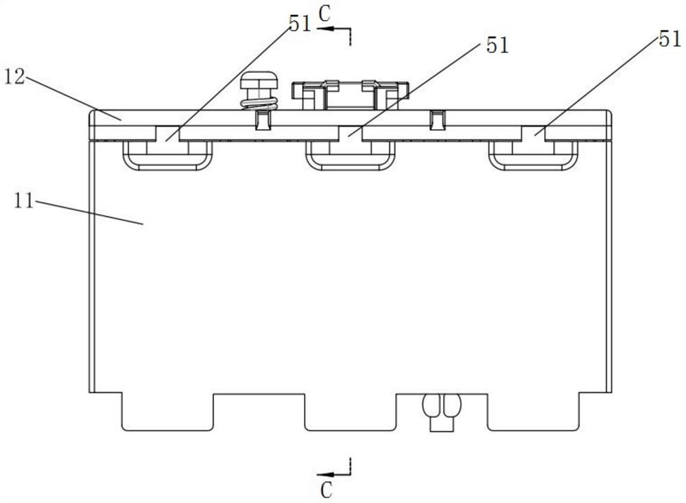
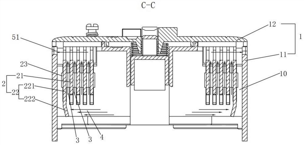
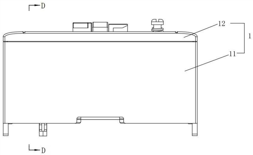
[0061] For the arc extinguishing system of this embodiment, see Figure 1 to Figure 13 As shown, it includes an arc extinguishing cover assembly 1 and an arc extinguishing blade assembly 2 . The arc extinguishing cover assembly 1 is provided with at least one arc extinguishing chamber 10 , and the arc extinguishing chamber 10 is provided with at least two mounting parts 13 arranged at intervals. The arc extinguishing plate assembly 2 includes at least one first arc extinguishing plate 21 and one second arc extinguishing plate 22, the first arc extinguishing plate 21 and the second arc extinguishing plate 22 are adapted to be respectively installed in the installation part 13, the first arc extinguishing plate The sheet 21 is arranged close to the movable contact 8 , and the second arc extinguishing sheet 22 is arranged away from the movable contact 8 . The space between two adjacent first arc extinguishing plates 21 and between the second arc extinguishing plate 22 and its ad...

Embodiment 2

[0068] The contactor of this embodiment, such as Figure 9 to Figure 13 As shown, it includes base assembly 7, base assembly 6 and the arc extinguishing system in Embodiment 1. Specifically, such as Figure 9 and Figure 11 As shown, the base assembly 7, the base assembly 6 and the arc extinguishing system are arranged in sequence from bottom to top. like Figure 10 As shown, the base assembly 6 includes a base, a contact assembly (not shown) and a contact support 61 disposed in the base. The base assembly 7 includes a base, a coil frame (not shown) and an iron core 71 disposed between the base and the coil frame, and the iron core 71 includes a yoke and a coil. The specific structure of the contact assembly is not described and limited in detail here, but it is a conventional contact structure in a contactor. Since the above-mentioned arc-extinguishing system is adopted, at least the advantages of the arc-extinguishing system of the above-mentioned embodiment 1 are obtai...


PUM


Abstract

The invention relates to the technical field of contactors and particularly relates to an arc extinguishing system and a contactor. The arc extinguishing system comprises an arc extinguishing cover assembly, wherein at least one arc extinguishing cavity is arranged in the arc extinguishing cover assembly, and at least two mounting parts arranged at intervals are arranged in the arc extinguishing cavity; the arc extinguishing sheet assembly comprises at least one first arc extinguishing sheet and one second arc extinguishing sheet which are suitable for being installed in the installation partrespectively, and a first arc supply channel is formed by the interval between any two adjacent first arc extinguishing sheets and the interval between the second arc extinguishing sheet and the firstarc extinguishing sheet adjacent to the second arc extinguishing sheet; the second arc extinguishing sheet comprises an arc extinguishing sheet body with the same height as the first arc extinguishing sheet and a bending part formed by bending and extending the lower end of the arc extinguishing sheet body towards the direction of the first arc extinguishing sheet or the moving contact, and the bending part, the bottom end of the first arc extinguishing sheet and an area among the contacts form an arc striking channel for introducing an arc into the first arc channel. The arc extinguishing system is advantaged in that a problem that an existing arc extinguishing sheet assembly needs to be riveted during installation, and consequently the rejection rate is high is solved.

Description

technical field [0001] The invention belongs to the technical field of contactors, and in particular relates to an arc extinguishing system and a contactor. Background technique [0002] A contactor is an electrical appliance used for long-distance and frequent switching on and off of AC and DC main circuits and large-capacity control circuits. Its main control object is the motor, and it can also be used to control electric heating equipment, electric lighting, and electric welding machines. and electrical loads such as capacitor banks. The contactor has a high operating frequency, the highest operating frequency can reach 1200 times per hour. In the circuit, the contactor is not required to have the ability to break the short-circuit current. When the circuit is short-circuited, it is protected by a fuse or a circuit breaker connected in series with the contactor. [0003] Contactors are divided into high-voltage and low-voltage contactors according to voltage levels; AC...

Claims


Application Information

Patent Timeline
Patent Type & Authority Applications(China)
IPC IPC(8): H01H9/34H01H50/00
CPCH01H9/34H01H50/00
Inventor 胡国伟张红伟荣良章王圳杰计新华张敏
Owner ZHEJIANG TENGEN ELECTRIC
Why Eureka
Try Eureka