Eureka AIR delivers breakthrough ideas for toughest innovation challenges, trusted by R&D personnel around the world.

Steady-state control method and steady-state control system for LiNbO3 optical switch for chopped pulse laser

A pulsed laser, steady-state control technology, applied in the field of optical fiber communication, can solve the problems of poor test accuracy and low extinction ratio, and achieve the effects of high extinction ratio, high detection accuracy and high stability

Active Publication Date: 2021-04-02
CHENGDU CHENGDIAN GUANGXIN TECH
View PDF9 Cites 0 Cited by
  • Summary
  • Abstract
  • Description
  • Claims
  • Application Information

AI Technical Summary

Problems solved by technology

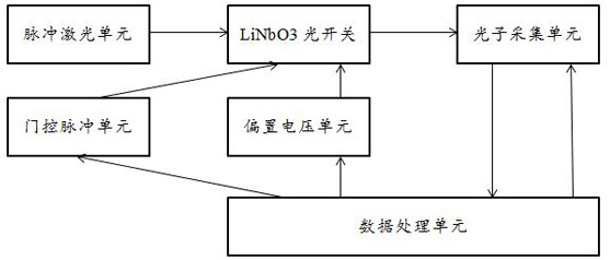
[0005] In view of this, the present invention provides a steady-state control method and system for a LiNbO3 optical switch of a fragmented pulsed laser, by defining a reference point and performing a voltage sweep test on the reference point to generate the optimal operating point of the optical switch, so that The optical switch is always stable in the best state, which solves the problems of poor test accuracy and low extinction ratio when the traditional steady-state control method of LiNbO3 optical switch is used for pulsed laser detection

Method used


Image

  • Steady-state control method and steady-state control system for LiNbO3 optical switch for chopped pulse laser
  • Steady-state control method and steady-state control system for LiNbO3 optical switch for chopped pulse laser

Examples


Embodiment Construction

[0019] In order to enable those skilled in the art to better understand the technical solution of the present invention, the present invention will be further described in detail below in conjunction with the accompanying drawings and specific embodiments.

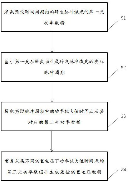
[0020] like figure 1 As shown, a steady-state control method for a LiNbO3 optical switch of a pulsed laser, including:

[0021] S1: When the LiNbO3 optical switch does not input the gate pulse, collect the first optical power data of the fragmented pulsed laser within a preset time period.

[0022] S2: Generate an actual pulse period of the split pulse laser based on the first optical power data. Wherein, the preset time period is greater than the actual pulse period; the data processing unit extracts a complete change period based on the time-varying trend of the first optical power data, that is, the actual pulse period.

[0023] S3: Extracting the power maximum time point in the actual pulse period and the correspondi...


PUM


Abstract

The invention discloses a steady-state control method and system of a LiNbO3 optical switch for chopped pulse laser. The steady-state control method comprises the following steps: acquiring first optical power data of the chopped pulse laser within a preset time period; generating an actual pulse period of the broken pulse laser based on the first optical power data; extracting a power maximum time point in the actual pulse period and second optical power data corresponding to the power maximum time point; and repeatedly acquiring third optical power data of the power maximum time point underdifferent bias voltages and generating optimal bias voltage data. According to the invention, the power maximum time point and the second optical power data corresponding to the power maximum time point are extracted by determining the actual pulse period of the broken pulse laser; in addition, the photon acquisition unit is controlled by the data processing unit to repeatedly acquire the third optical power data of the power maximum time point under different bias voltages so as to extract the optimal bias voltage data, so that the high extinction ratio, high stability and high detection precision of the whole detection system are ensured.

Description

technical field [0001] The invention relates to the technical field of optical fiber communication, in particular to a steady-state control method and system for a LiNbO3 optical switch used for bursting pulsed lasers. Background technique [0002] LiNbO3 modulators are usually used as external modulators for optical transmitters in optical fiber communication systems, and can also be used as high-speed optical switches. Since the optical waveguide of the LiNbO3 modulator is greatly affected by the environment, the working state is unstable. Therefore, in practical applications, in addition to using the modulation signal electrode to act on the optical waveguide, it is also necessary to increase the bias voltage electrode to act on the optical waveguide, and adjust the device to Appropriate working conditions to ensure the extinction ratio or linearity of the modulator. Traditional optical fiber transmission digital systems or analog systems have sufficient average optical ...

Claims


Application Information

Patent Timeline
Patent Type & Authority Applications(China)
IPC IPC(8): H03K17/945
CPCH03K17/945
Inventor 解军阳树中
Owner CHENGDU CHENGDIAN GUANGXIN TECH
Why Eureka
Eureka Blog
Learn More