Supercharge Your Innovation With Domain-Expert AI Agents!

RFOG optical receiver circuit

A technology of optical receiver and photoelectric conversion circuit, which is applied in the direction of electromagnetic receiver, TV system adapted to optical transmission, cable transmission adaptation, etc., can solve the problems of front-end computer room service and manufacturing cost increase, large convergence noise, etc., and achieve high cost performance , reduce the aggregation noise, and realize the effect of effective transmission

Pending Publication Date: 2021-04-02
无锡雷华网络技术有限公司
View PDF0 Cites 0 Cited by
  • Summary
  • Abstract
  • Description
  • Claims
  • Application Information

AI Technical Summary

Problems solved by technology

However, the mixed output optical receiver of the return signal currently on the market is in the working state for a long time, and the convergence noise of four receiving and one output is large; the number of others will increase, resulting in an increase in the service and manufacturing costs of the front-end computer room

Method used


Image

  • RFOG optical receiver circuit
  • RFOG optical receiver circuit
  • RFOG optical receiver circuit

Examples


Embodiment Construction

[0015] In order to make the object, technical solution and advantages of the present invention clearer, the present invention will be described in further detail below in conjunction with specific embodiments and with reference to the accompanying drawings.

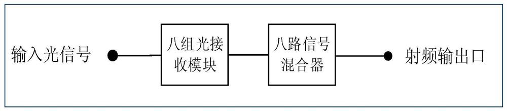
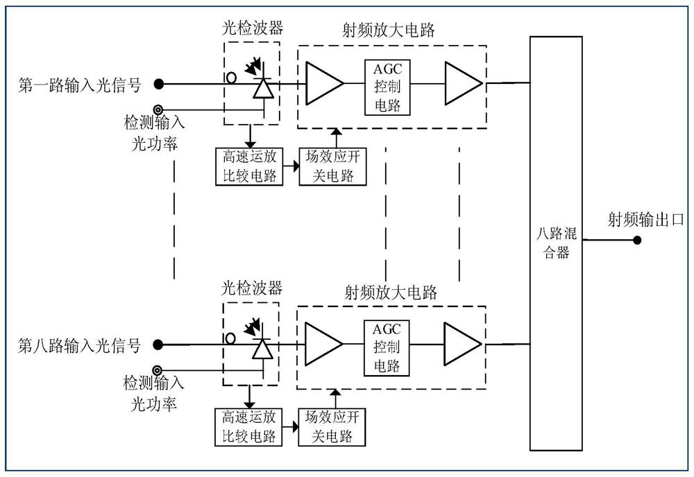
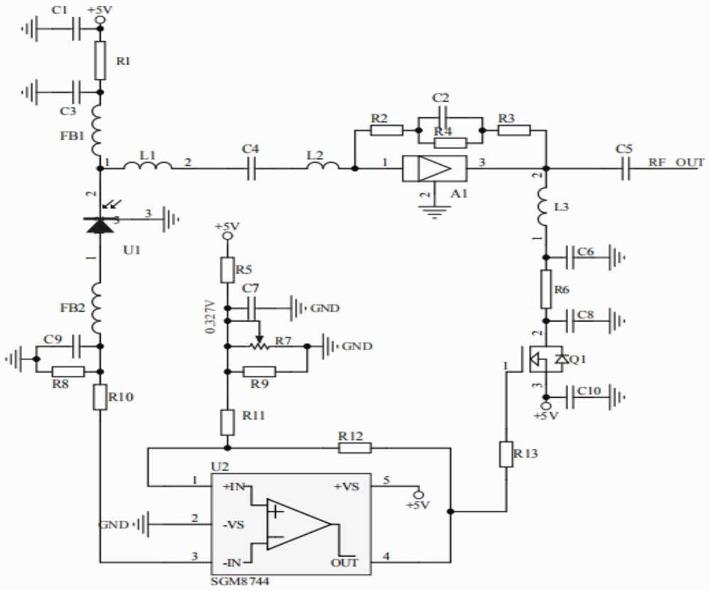
[0016] Such as figure 1 Shown: the present invention includes eight input optical signals, eight groups of optical receiver circuits and eight mixers. The eight input optical signals are respectively connected to eight groups of optical receiver circuits through signal lines, and the eight groups of optical receiver circuits are respectively connected to eight-way mixers through signal lines, and the eight-way mixers are connected to radio frequency output ports through signal lines, thereby forming a whole The controlled closed-loop circuit realizes the high-speed switching of eight-way return signals and realizes the effective transmission of multi-channel signals. The eight groups of optical receiver circuits in the p...


PUM


Abstract

The invention relates to an RFOG optical receiver circuit, and belongs to the technical field of radio and television RFOG transmission. The system comprises eight paths of input optical signals, eight groups of optical receiver circuits and eight paths of mixers; wherein the eight paths of input optical signals are respectively connected with the eight groups of optical receiver circuits throughsignal lines, the eight groups of optical receiver circuits are respectively connected with the eight paths of mixers through signal lines, and the eight paths of mixers are connected with the radio frequency output port through signal lines, so that a controlled closed-loop circuit is formed. One group of optical receiver circuits comprises a first path of input optical signal, a photoelectric conversion circuit, a radio frequency amplification circuit, a high-speed operational amplifier comparison circuit, a field effect switch circuit and a path of mixer. According to the invention, eight-path mixed output, high-speed switching of eight-path return signals and effective transmission of multiple paths of signals can be realized, the cost performance is high, excellent indexes are ensured, the convergence noise is effectively reduced, and a user can watch CATV programs only by installing one light spot converter.

Description

technical field [0001] The invention relates to an RFOG optical receiver circuit, in particular to a high-frequency transmission system related to the RFOG optical receiver circuit, and belongs to the technical field of radio and television RFOG transmission. Background technique [0002] With the development of the communication industry, the use of network transmission is diversified. RFOG is used to define a PON network architecture, which can transmit voice, video and DOCSIS-based data on optical fibers. Install a small RFOG transmitter in each household to send optical signals, and the optical signals are transmitted back to the front-end server through optical fibers, which requires a multi-channel return signal mixed output optical receiver. However, what is mainly realized in the market at present is to collect once and output once, collect twice and output one, and collect four and output once. The number of devices, power consumption, and price are all big expens...

Claims


Application Information

Patent Timeline
Patent Type & Authority Applications(China)
IPC IPC(8): H04B10/60H04N7/22
CPCH04B10/60H04N7/22
Inventor 万年飞林文军张满根
Owner 无锡雷华网络技术有限公司
Features
  • R&D
  • Intellectual Property
  • Life Sciences
  • Materials
  • Tech Scout
  • Unparalleled Data Quality
  • Higher Quality Content
  • 60% Fewer Hallucinations
Learn More