Eureka AIR delivers breakthrough ideas for toughest innovation challenges, trusted by R&D personnel around the world.

Waste recovery mechanism of hardware building material grinding device and working method of waste recovery mechanism

A waste recycling and grinding machine technology, applied in grinding/polishing safety devices, liquid cleaning methods, grinding racks, etc., can solve the problem that dust and waste cannot be separated, increase the workload of staff, and poor cleaning effect And other issues

Inactive Publication Date: 2021-04-06
马鞍山凯宁环保科技有限公司
View PDF0 Cites 3 Cited by
  • Summary
  • Abstract
  • Description
  • Claims
  • Application Information

AI Technical Summary

Problems solved by technology

[0003] However, the recycling method of the waste recycling mechanism generally requires manual cleaning, which leads to the concentration of the inside of the recycling mechanism, resulting in low recycling efficiency, and increases the workload of the staff, reducing work efficiency, and there is no cleaning device, resulting in no dust on the waste. Cleaning, the recovered waste cannot be used directly, and generally there is no filter device, resulting in the inability to separate the dust and waste after cleaning, resulting in a part of the dust remaining, resulting in poor cleaning effect

Method used


Image

  • Waste recovery mechanism of hardware building material grinding device and working method of waste recovery mechanism
  • Waste recovery mechanism of hardware building material grinding device and working method of waste recovery mechanism
  • Waste recovery mechanism of hardware building material grinding device and working method of waste recovery mechanism

Examples


Embodiment Construction

[0025] The following will clearly and completely describe the technical solutions in the embodiments of the present invention with reference to the accompanying drawings in the embodiments of the present invention. Obviously, the described embodiments are only some, not all, embodiments of the present invention. Based on the embodiments of the present invention, all other embodiments obtained by persons of ordinary skill in the art without making creative efforts belong to the protection scope of the present invention.

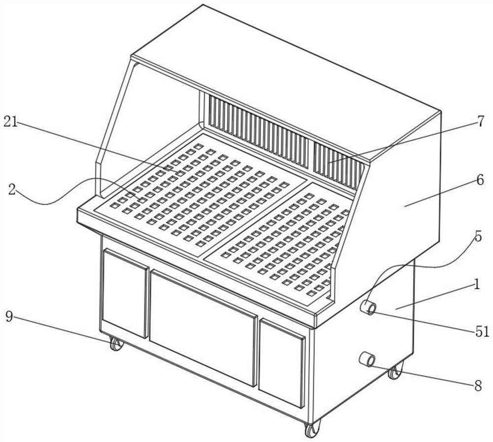
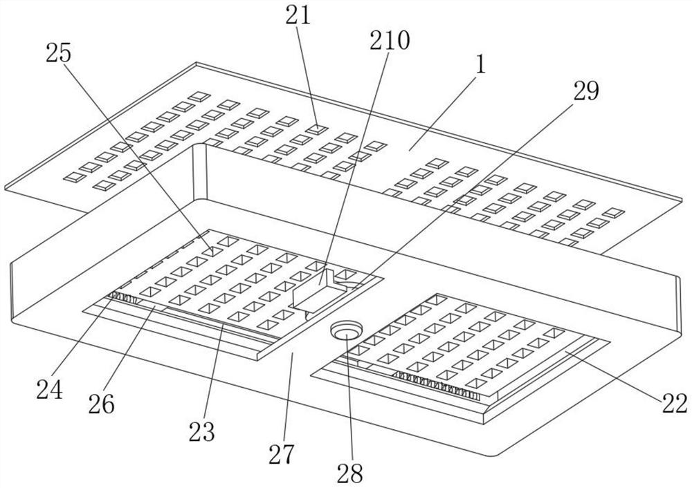
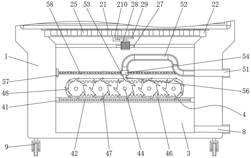
[0026] see Figure 1-5 , the present invention provides a technical solution: a waste material recycling mechanism for a hardware and building material grinding device, including a grinding machine main body 1, a recycling assembly 2 is fixed inside the top end of the grinding machine main body 1, and a bottom end of the grinding machine main body 1 There is a cleaning tank 3 inside, and a filter assembly 4 is fixed inside one side of the cleaning tank 3, and ...


PUM


Abstract

The invention discloses a waste recovery mechanism of a hardware building material grinding device and a working method of the waste recovery mechanism. The waste recovery mechanism comprises a grinding machine body, wherein a recovery assembly is fixed in the top end of the grinding machine body, a cleaning tank is formed in the bottom end of the grinding machine body, and a filtering assembly is fixed in one side of the cleaning tank; a cleaning assembly is fixed in one side of the cleaning tank; and the recovery assembly comprises feeding holes distributed in the top end of the plate surface of the grinding machine body, a mounting groove is formed in the part, located at the bottom ends of the feeding holes, of the grinding machine body, and a feeding plate is mounted in one side of the mounting groove. According to the waste recovery device, waste can be automatically recovered through the recovery device, manual assistance is not needed, the recovery efficiency is improved, the workload of workers is reduced, and the working efficiency is improved; and the waste can be cleaned more comprehensively through the cleaning device, dust on the waste can be cleaned conveniently, and the recovered waste can be directly used conveniently.

Description

technical field [0001] The invention belongs to the technical field of grinding equipment, in particular to a waste material recycling mechanism of a hardware building material grinding device and a working method thereof. Background technique [0002] Hardware building materials refer to traditional hardware products, also known as "small hardware"; refer to five metals: gold, silver, copper, iron, and tin; through manual processing, they can be made into knives, swords and other works of art or metal devices; hardware in modern society is more It is widely used, such as hardware tools, hardware parts, daily hardware, construction hardware and security supplies, etc.; most of the small hardware products are not final consumer goods, and the production of hardware and building materials requires a grinding device, and a lot of waste will be generated after grinding. At this time, waste is needed recycling agency. [0003] However, the recycling method of the waste recycling...

Claims


Application Information

Patent Timeline
IPC IPC(8): B24B19/00B24B41/02B24B55/12B07B1/04B08B3/02B08B13/00
CPCB07B1/04B08B3/022B08B13/00B24B19/00B24B41/02B24B55/12Y02P70/10
Inventor 范士金游登洲沈玉鹏刘成
Owner 马鞍山凯宁环保科技有限公司
Why Eureka
Eureka Blog
Learn More