Cutting equipment for sponge mat production
A technology of cutting equipment and sponge pads, which is applied in metal processing and other directions, can solve the problems of low work efficiency, troublesome operation, easy shaking of hands, etc., and achieve the effects of high work efficiency, convenient operation and convenient collection
- Summary
- Abstract
- Description
- Claims
- Application Information
AI Technical Summary
Problems solved by technology
Method used
Image

Examples
Embodiment 1
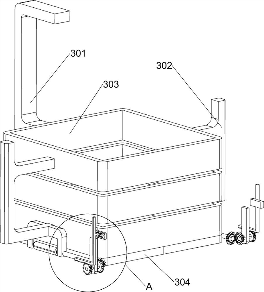
[0029] A cutting device for the production of sponge pads, such as figure 1 , figure 2 , image 3 , Figure 4 with Figure 9 As shown, it includes a base 1, a first support frame 2, a placement assembly 3 and a cutting assembly 4. The top of the base 1 is symmetrically provided with a first support frame 2, and the first support frame 2 is provided with a placement assembly 3, and the placement assembly 3 There is a cutting assembly 4 on it.
[0030] The placement assembly 3 includes a second support frame 301, a third support frame 302, a placement frame 303, a baffle plate 304, a first rotating shaft 305 and a torsion spring 306, and a third support frame is fixed in the middle of the top of the first support frame 2 302, a placement frame 303 is fixed symmetrically between the inner ends of the third support frame 302 on the left and right sides, and a second support frame 301 is fixed between the middle of the rear side of the frame 303 on the upper and lower sides, a...
Embodiment 2
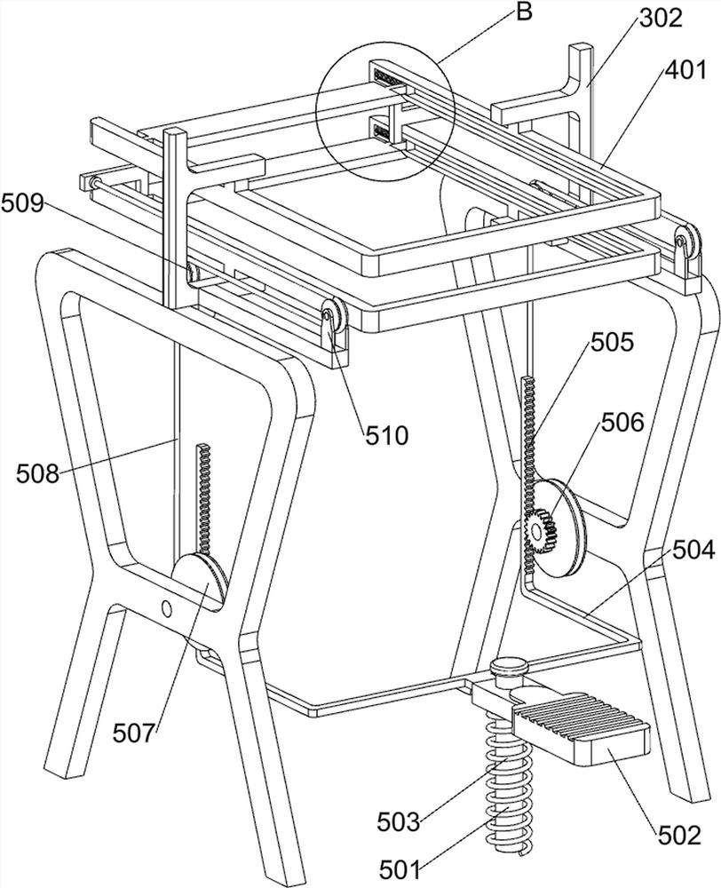
[0036] On the basis of Example 1, such as figure 1 , figure 2 , Figure 4 , Figure 5 , Image 6 with Figure 8 As shown, it also includes a stepping assembly 5, and the stepping assembly 5 includes a guide rod 501, a pedal 502, a second spring 503, a second connecting rod 504, a first rack 505, a first gear 506, a winding wheel 507, a pulley Rope 508, first pulley 509 and second pulley 510, base 1 top front side middle part is fixedly connected with guide rod 501, guide rod 501 is provided with pedal 502 slidingly, pedal 502 bottom rear side and base 1 top front side middle part The second spring 503 is fixedly connected between them, the second spring 503 is set on the guide rod 501, the rear part of the pedal 502 is fixedly connected with the second connecting rod 504, and the rear part of the second connecting rod 504 is symmetrically connected with the first rack 505 The middle part of the inner surface of the first support frame 2 is rotatably provided with a windi...
Embodiment 3
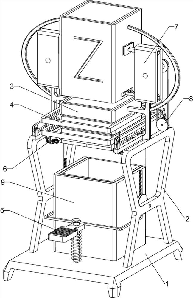
[0045] On the basis of embodiment 1 and embodiment 2, such as figure 1 with Figure 7 As shown, a collection assembly 9 is also included. The collection assembly 9 includes a limit frame 901, a collection frame 902 and a handle 903. The limit frame 901 is fixed in the middle of the top of the base 1, and a collection frame 902 is slidably placed in the limit frame 901. A handle 903 is affixed to the central part of the outer rear side of the collection frame 902 .
[0046]After the sponge cutting is completed, the sponge falls into the collection frame 902, and when there is an appropriate amount of sponge in the collection frame 902, pull the handle 903 to take out the collection frame 902 for subsequent processing of the sponge, and then put the collection frame 902 back to the limit In the frame 901, it is convenient for people to collect the cut sponges.
PUM
 Abstract
Description
Claims
Application Information
 - R&D
- Intellectual Property
- Life Sciences
- Materials
- Tech Scout
- Unparalleled Data Quality
- Higher Quality Content
- 60% Fewer Hallucinations
Browse by: Latest US Patents, China's latest patents, Technical Efficacy Thesaurus, Application Domain, Technology Topic, Popular Technical Reports.
© 2025 PatSnap. All rights reserved.Legal|Privacy policy|Modern Slavery Act Transparency Statement|Sitemap|About US| Contact US: help@patsnap.com