
Torsion beam rear axle

A torsion beam and rear axle technology, applied in the field of vehicle engineering, can solve problems such as poor reliability, fatigue cracking at the welding position of the stabilizer bar, and affect the connection strength of the main beam and the trailing arm, etc., so as to improve fatigue performance and avoid abnormal noise.

Pending Publication Date: 2021-04-06
宁波可挺汽车零部件有限公司
View PDF4 Cites 0 Cited by
  • Summary
  • Abstract
  • Description
  • Claims
  • Application Information

AI Technical Summary

Problems solved by technology

The structure of the existing torsion beam rear axle is either that the entire main beam adopts a back-shaped closed hollow beam, or an open beam with a stabilizer bar welded in it, but the torsion beam is often torsion during use. This will lead to fatigue cracking at the welding position of the stabilizer bar, affecting the connection strength between the main beam and the trailing arm, and poor reliability

Method used


Image

  • Torsion beam rear axle
  • Torsion beam rear axle
  • Torsion beam rear axle

Examples


Embodiment Construction

[0023] The technical solutions of the various embodiments of the present invention will be clearly and completely described below in conjunction with the accompanying drawings. Apparently, the described embodiments are only some of the embodiments of the present invention, not all of them. Based on the embodiments described in the present invention, all other embodiments obtained by persons of ordinary skill in the art without creative work are within the protection scope of the present invention.

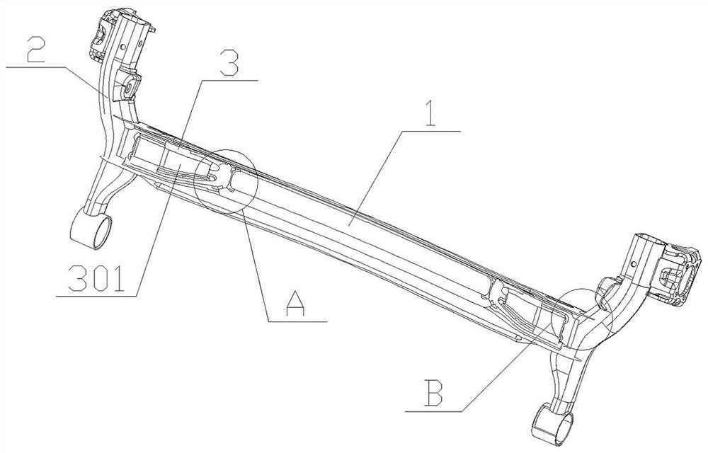
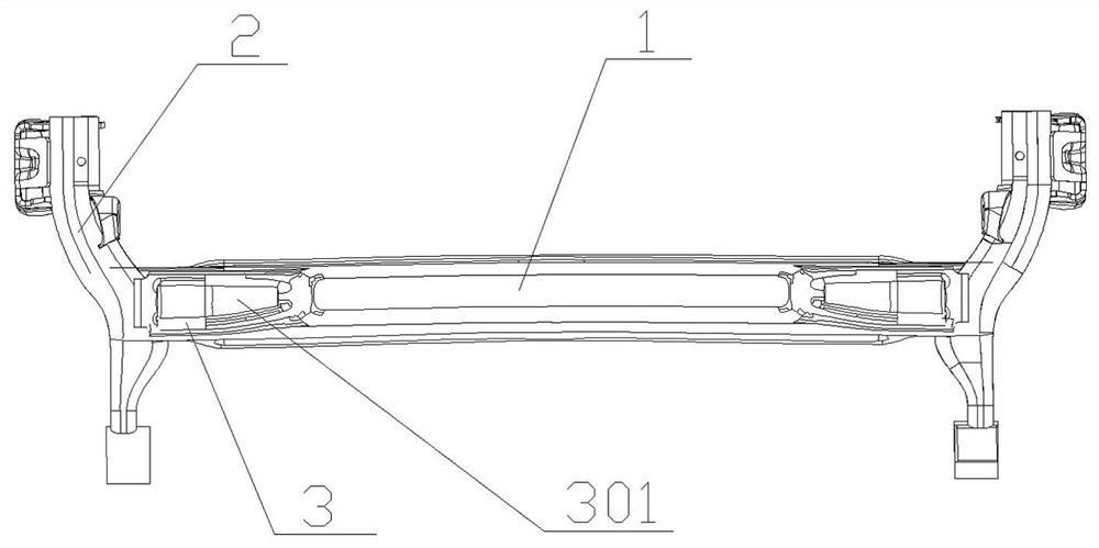
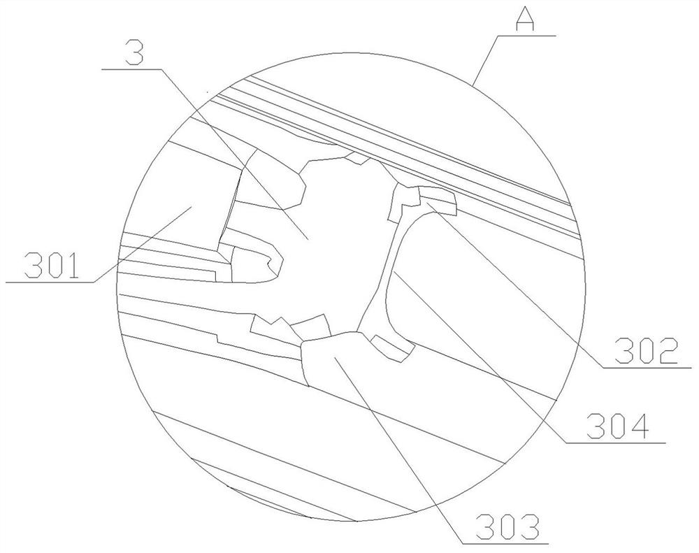
[0024] Example Figure 1 to Figure 4 As shown, a torsion beam rear axle includes a main beam 1 and a longitudinal arm 2. The main beam 1 has a U-shaped section and a U-shaped groove. Both sides of the main beam 1 are provided with arc-shaped grooves. The longitudinal The arm 2 and the main beam 1 are fixedly connected by welding through the arc-shaped groove, and both ends of the U-shaped groove are welded with a reinforcement plate 3 , and the reinforcement plate 3 is also welded ...


PUM


Abstract

A torsion beam rear axle is disclosed in the invention, and comprises a main beam and longitudinal arms, the section of the main beam is in a U shape and is provided with a U-shaped groove, arc-shaped grooves are formed in the two sides of the main beam, the longitudinal arms are fixedly connected with the main beam through the arc-shaped grooves in a welded mode, reinforcing plates are welded to the two ends in the U-shaped groove, and the reinforcing plates are further welded to the longitudinal arms. The reinforcing plates are welded in the U-shaped groove of the main beam to replace an existing stabilizer bar, the rigidity of the main beam is improved while the weight of the main beam is reduced, and abnormal sounds generated by installation of the stabilizer bar are avoided. Meanwhile, a convex plate, a notch and an arc-shaped edge are arranged at the welding position of the reinforcing plates and the U-shaped grooves, local stress at the welding position can be dispersed and evenly distributed on the reinforcing plates, the fatigue performance is improved, extending edges are arranged on the two sides of the main beam, local stress at the welding position of the main beam and the longitudinal arm is dispersed, so the welding wires are uniformly distributed on the extending edges, and the fatigue of the welding position is improved.

Description

technical field [0001] The invention relates to the field of vehicle engineering, in particular to a torsion beam rear axle. Background technique [0002] Along with the raising of living standard, people more and more have purchased automobile as means of transportation, and suspension is all installed on the automobile, guarantees that vehicle does not produce roll when driving on uneven road surface. Torsion beam suspension is a type of rear suspension of automobiles. It uses a torsion beam shaft to balance the up and down jump of the left and right wheels to reduce the shaking of the vehicle and keep the vehicle stable. It is a type of non-independent suspension. Its work The principle is to install non-independently suspended wheels on both ends of a torsion beam. When one wheel jumps up and down, the torsion beam will jump around the axis, which will drive the other side of the wheel to jump accordingly, reducing the inclination or shake. The structure of the existin...

Claims


Application Information

Patent Timeline
Patent Type & Authority Applications(China)
IPC IPC(8): B60G11/18B60G11/20
CPCB60G11/183B60G11/20B60G2202/134
Inventor 唐长刚孙胜喜汪建军吴少坤
Owner 宁波可挺汽车零部件有限公司
Learn More