
Method and device for detecting poor shunting of track circuit

A track circuit and bad shunting technology, which is applied in electronic circuit testing, railway signals, transportation and packaging, etc., can solve problems such as disjointed production processes, threats to the safety of train receiving and dispatching and shunting operations, and bad shunting, so as to eliminate The hazards of driving operations, meeting the needs of transportation and production, and the effect of ensuring the safety of driving operations

Active Publication Date: 2021-04-06
宣化钢铁集团有限责任公司
View PDF9 Cites 0 Cited by
  • Summary
  • Abstract
  • Description
  • Claims
  • Application Information

AI Technical Summary

Problems solved by technology

However, in areas with less work in metallurgical enterprises, due to dust pollution, rusted rails, and rusted rail surfaces in rainy seasons, the track relay cannot be dropped when the track circuit section is occupied by cars, and there is a bad shunt. This is also commonly referred to as "" "Undead" phenomenon
Track circuit equipment cannot correctly reflect the occupancy of railway lines, the interlocking function of electrical centralized equipment fails, and the console display is distorted, which in turn has a serious impact on driving safety and directly threatens the safety of receiving and dispatching trains and shunting operations. There have been many accidents of jamming and derailment caused by poor circuit shunting in recent years
And it caused the disconnection of the company's production process chain, which became an urgent problem to be solved.

Method used


Image

  • Method and device for detecting poor shunting of track circuit
  • Method and device for detecting poor shunting of track circuit
  • Method and device for detecting poor shunting of track circuit

Examples


Embodiment Construction

[0018] In order to make the purposes, technical solutions and advantages of the implementation cases of the invention clearer, the following will combine the accompanying drawings in the implementation cases to clearly and completely describe the technical solutions in the implementation cases of the present invention. A small part of the implementation cases of the invention, not all of the implementation cases, based on the implementation cases in the present invention, all other implementation cases obtained by those of ordinary skill in the art without creative work, belong to the protection scope of the present invention.

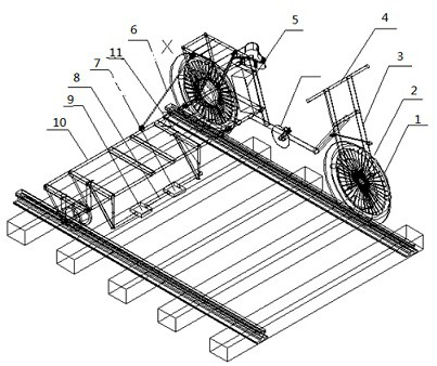
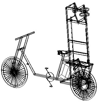
[0019] A method for detecting poor shunting of a track circuit, comprising the following steps: including a detection body and a detection running device, (1) detecting that the running device is walking on a track, and by short-circuiting the track circuit to simulate a train to detect the shunt state of the track circuit; ( 2) The detection body colle...


PUM

PropertyMeasurementUnit
Lengthaaaaaaaaaa
Length and widthaaaaaaaaaa
Thicknessaaaaaaaaaa

Abstract

The invention relates to a method and device for detecting poor shunting of a track circuit, and belongs to the technical field of railway signal maintenance. According to the technical scheme, a detection operation device walks on a track, and the shunting state of a train detection track circuit is simulated by short-circuiting the track circuit; a detection body collects shunt voltages in time through a voltage sensor, then amplifies signals through an amplifier, compares the amplified signals with a set value, and if the actual value is higher than the set value, the detection body does not change. And if the actual value is lower than the set value, the detection body sends a sound-light alarm through the alarm module to prompt that the shunting of the track circuit is poor. The method has the advantages that whether faults of poor shunting of the track circuit exist in different track sections or not can be timely and accurately diagnosed, the names of the poor shunting sections of the track circuit can be locked, and therefore the safety of driving operation and the right point of pulling and exchanging operation are guaranteed.

Description

technical field [0001] The invention relates to a method and a device for detecting faulty track circuit shunting, and belongs to the technical field of railway signal maintenance. Background technique [0002] The railway track circuit is a circuit composed of two rails as conductors, both ends are insulated by rails, and connected to power transmission and power receiving equipment. It plays the role of supervising and checking whether the line is occupied. However, in areas with less work in metallurgical enterprises, due to dust pollution, rusted rails, and rusted rail surfaces in rainy seasons, the track relays cannot fall when the track circuit section is occupied by vehicles, resulting in poor shunts, which is also commonly referred to as "" can't die" phenomenon. The track circuit equipment cannot correctly reflect the occupancy of the railway line, the interlocking function of the electrical centralized equipment fails, and the console display is distorted, which ...

Claims


Application Information

Patent Timeline
IPC IPC(8): B61L1/02G01R31/28
CPCB61L1/02G01R31/28
Inventor 张彦青王宏斌郭瑛张磊王亚君李永红牟清国杜茂权者菲菲程栋桥
Owner 宣化钢铁集团有限责任公司
Learn More