Automatic charging system for rotor unmanned aerial vehicle

A technology of unmanned rotor and charging system, applied in electric vehicle charging technology, charging stations, motor vehicles, etc., can solve the problem that the drone cannot be accurately aligned with the charging head, the battery life is short, and the automatic battery charging cannot be completed. question

Active Publication Date: 2021-04-06
云南尼古拉智能科技有限公司
View PDF8 Cites 0 Cited by
  • Summary
  • Abstract
  • Description
  • Claims
  • Application Information

AI Technical Summary

Problems solved by technology

According to statistics, electric motors are widely used as the power system for drones, and the battery life is generally short. It needs to be recharged or replaced after landing before it can be put into use again. It needs manual assistance from the user, which makes it unable to complete fully automatic battery life charging. Now the multi-rotor drones on the market can complete a certain degree of vertical take-off and landing, but in the face of the point-to-point requirements of automatic charging of drones, it is still Unable to achieve accurate automatic battery life charging

Method used


Image

  • Automatic charging system for rotor unmanned aerial vehicle
  • Automatic charging system for rotor unmanned aerial vehicle
  • Automatic charging system for rotor unmanned aerial vehicle

Examples


Embodiment Construction

[0027]In order to make the purpose, technical solutions and advantages of the embodiments of the present invention clearer, the technical solutions in the embodiments of the present invention will be clearly and completely described below in conjunction with the drawings in the embodiments of the present invention. Obviously, the described embodiments It is a part of embodiments of the present invention, but not all embodiments. The components of the embodiments of the invention generally described and illustrated in the figures herein may be arranged and designed in a variety of different configurations.

[0028] Accordingly, the following detailed description of the embodiments of the invention provided in the accompanying drawings is not intended to limit the scope of the claimed invention, but merely represents selected embodiments of the invention. Based on the embodiments of the present invention, all other embodiments obtained by persons of ordinary skill in the art wit...


PUM


Abstract

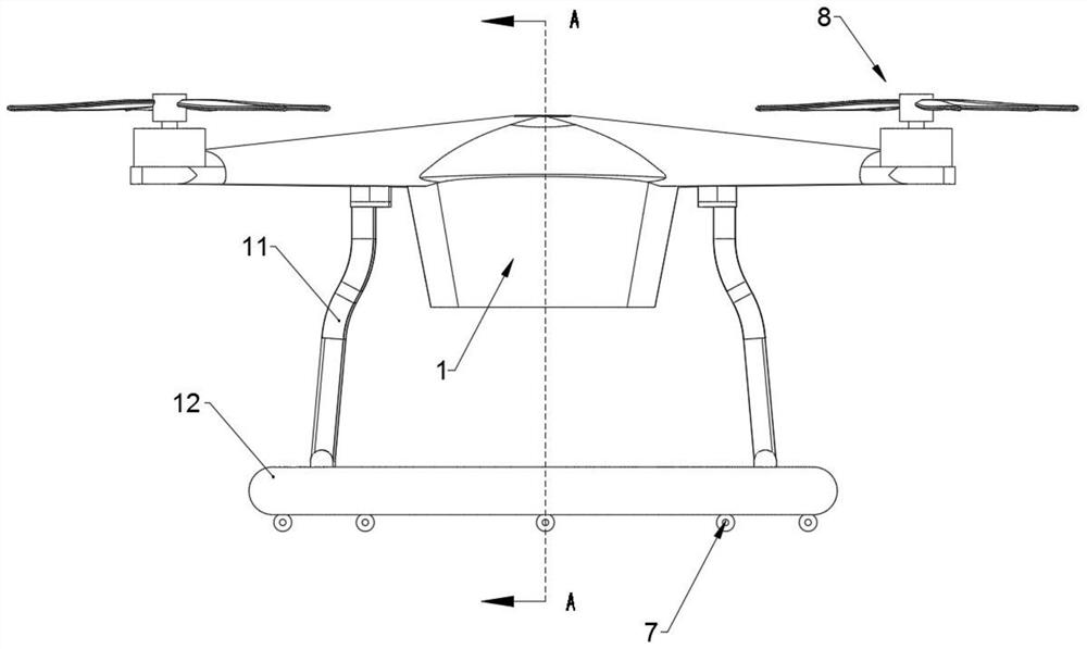
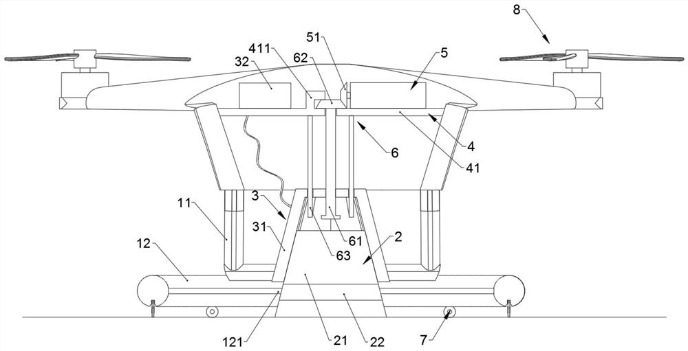
The invention discloses an automatic charging system for a rotor unmanned aerial vehicle, and relates to the technical field of unmanned aerial vehicle charging, the automatic charging system comprises a rotor unmanned aerial vehicle body and a charging seat, the rotor unmanned aerial vehicle body is internally provided with a charging assembly and a supporting structure, the supporting structure is provided with a power module, the power module is connected with a lifting assembly, and the lifting assembly is connected with the charging assembly; the charging assembly comprises a charging table, and a charging cavity is formed in the bottom of the charging table and provided with an upper electrode connecting piece; a lower electrode contact pin is arranged at the middle upper part of the outer side surface of the charging seat which is in the shape of a circular truncated cone, and a detection head is arranged at the lower part of the outer side surface of the charging seat; supporting legs extending downwards are arranged at the bottom of the rotor unmanned aerial vehicle body, a horizontal positioning ring is arranged at the bottoms of the supporting legs, a circle of detection strip is arranged on the inner wall of the horizontal positioning ring, and a plurality of universal wheel sets are arranged at the bottom of the horizontal positioning ring. The system has the advantages of being high in automation level, high in charging efficiency and good in charging effect.

Description

technical field [0001] The invention relates to the technical field of unmanned aerial vehicle charging, in particular to an automatic charging system for a rotor unmanned aerial vehicle. Background technique [0002] With the continuous maturity and development of UAV technology, UAVs are widely used in civilian applications due to their relatively low cost, no risk of casualties, strong survivability, good maneuverability, and convenient use. The main application markets include: aerial photography, aerial photography, geological and landform surveying, forest fire prevention, earthquake investigation, nuclear radiation detection, border patrol, emergency relief, crop yield estimation, farmland information monitoring, pipeline, high-voltage transmission line inspection, wildlife protection, Scientific research experiments, maritime reconnaissance, fish situation monitoring, environmental monitoring, atmospheric sampling, rainfall enhancement, resource exploration, drug con...

Claims


Application Information

Patent Timeline
Patent Type & Authority Applications(China)
IPC IPC(8): B64C39/02B60L53/12B60L53/122B60L53/38B60L53/126H02J50/10H02J50/90
CPCB64C39/02B60L53/12B60L53/122B60L53/38B60L53/126H02J50/10H02J50/90B60L2200/10B64U10/10Y02T90/12
Inventor 王维
Owner 云南尼古拉智能科技有限公司
Why Eureka
Try Eureka