Packaging lining plate

A liner and packaging technology, which is applied in the field of packaging liners, can solve problems such as sharp corners, product defects, and breakage of card slot tabs, to ensure safety and effectiveness, short disassembly strokes, and smooth and simple operations Effect

Pending Publication Date: 2021-04-06
NINGBO DIOCHANGE MEDICAL TECH CO LTD
View PDF1 Cites 0 Cited by
  • Summary
  • Abstract
  • Description
  • Claims
  • Application Information

AI Technical Summary

Problems solved by technology

[0003] Take the commonly used "disc cover" left atrial appendage occluder as an example, which includes two parts, the anchor frame and the occlusion disk. The anchor frame is usually equipped with a tip barb for anchoring the left atrial appendage. When squeezed, the barbs on the anchoring frame can easily puncture the flow-blocking membrane on the blocking disc, resulting in product defects. At the same time, the product may not return to its original shape or even break after being squeezed for a long time. lead to potential safety hazards in the product
These problems are fatal to the occluder. Once the defective occluder is implanted in the patient's body, it will cause irreparable damage to the patient's life and health.
The existing packaging design on the market is relatively complicated, and the protection range is limited, and it is difficult for users to operate, and it is difficult to solve the problems faced by the product in the existing packaging method. For example, the patent CN209650816U relates to a packaging partition, which has The following questions:
[0004] Before assembly: a) The shape of the two slot tabs of the upper partition is T-shaped, the shape of the receiving openings of the two slots of the lower partition is double L-shaped, and the width of the two slot tabs of the upper partition is larger than that of the lower partition The width of the receiving openings of the two double L-shaped card slots on the panel requires that the card slot tabs of the upper partition be forcibly bent before they can be put into the receiving openings of the lower partition board. The bent tabs of the card slots will Form sharp corners and damage the objects to be packaged; b) The two slot tabs of the upper partition and the two double L shapes of the lower partition are rotating structures (need to rotate 90°), so that the objects to be packaged and the rotating structure need to be kept Only a certain distance can ensure that the goods to be packaged are not affected, thereby increasing the design space of the lower partition and increasing the cost; c) The bending structure of the lower partition is only formed by bending a flat sheet, and the strength is insufficient, and it will grow after bending. There will be a certain recovery effect under static time, which will cause the deformation of the protective cavity formed by the bending structure, and cannot effectively protect the object to be packaged

Method used


Image

  • Packaging lining plate
  • Packaging lining plate
  • Packaging lining plate

Examples


Embodiment 1

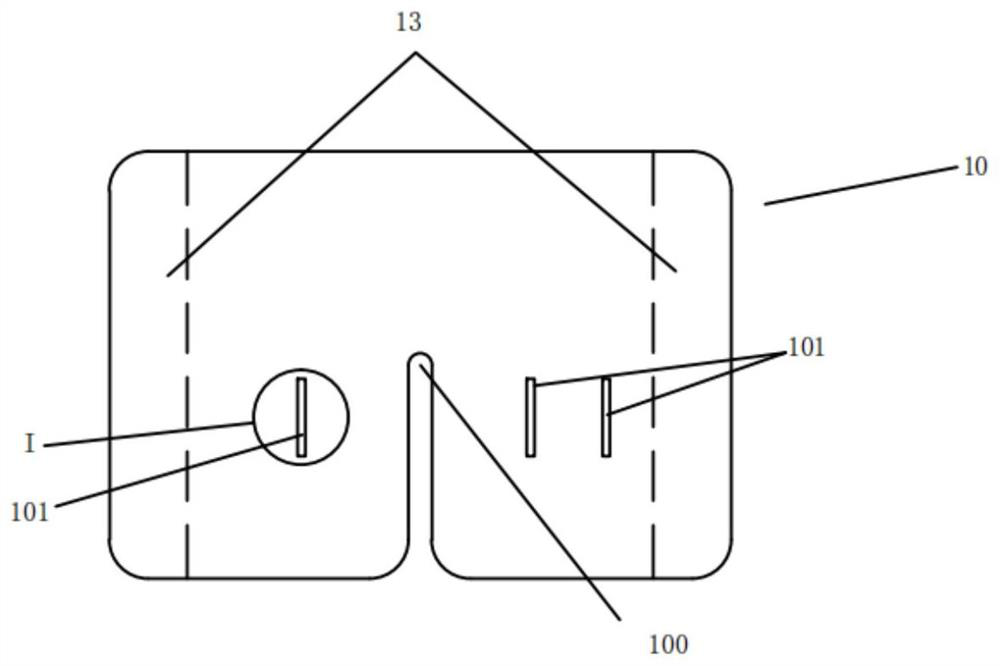
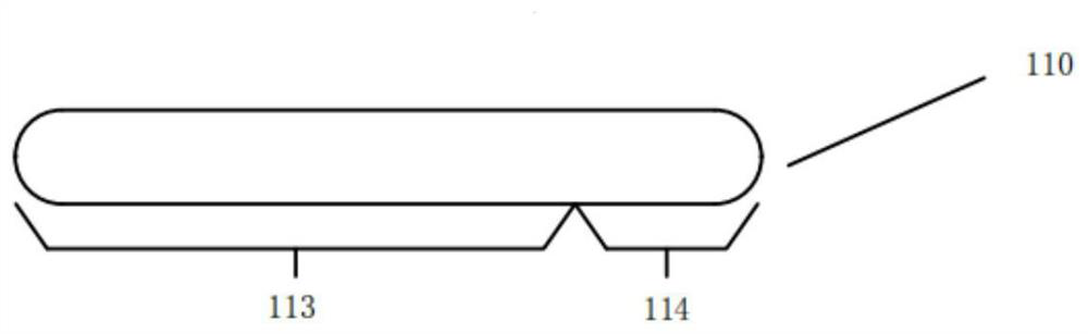
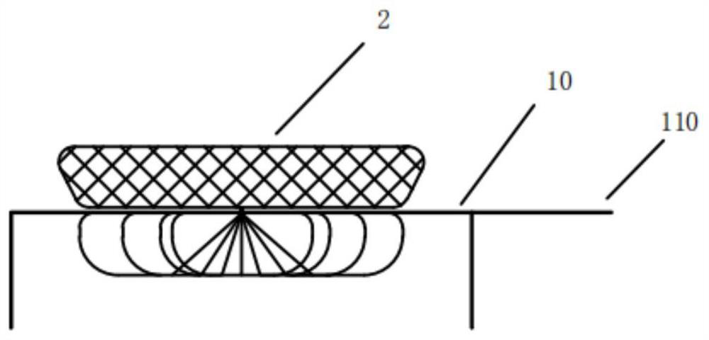
[0089] Figure 1a Shown is a schematic diagram of a packaging liner 1 in this embodiment, including a carrying plate 10 and a limiting member 11, a storage slot 100 is provided on the loading plate 10, and the object to be packaged 2 is at least partially placed in the storage slot 100 The limiting member 11 includes a fitting part 113 and a gripping part 114. The fitting part 113 is at least partly fitted to the bearing plate 10. The gripping part 114 can be freed from the bearing plate 10. The bearing plate 10 is provided with a The groove structure 12 that cooperates with the joint portion 113 realizes the assembly and disassembly functions of the two through horizontal sliding. With respect to the carrier plate 10, the sliding direction of the limiting member 11 is not parallel to the initial direction of taking out the packaged object 2, and the sliding direction is defined. The angle between the direction and the initial direction of taking out is θ, and θ satisfies the f...

Embodiment 2

[0092] like Figure 4a and 4b As shown, this embodiment is based on Embodiment 1. The difference between this embodiment and Embodiment 1 is that: one end of the fitting part 113 of the limit drawer 110 is provided with a limit protrusion 1101, which is used to realize the limit drawer The gripping part 114 of 110 moves in a single direction relative to the carrier plate 10, which is convenient for the operator to intuitively judge the extraction direction of the limit drawer 110. The other end of the fitting part 113 is provided with a protruding structure 1100. The protruding structure 1100 and The hole groove 101 on the carrier plate 10 adopts interference fit or transition fit, which is used to prevent the joint part 113 and the carrier plate 10 from sliding or shaking in a natural state, and can effectively protect the object to be packaged 2, such as Figure 4a and 4b shown.

[0093] At this time, define the horizontal spacing between the limiting protrusion 1101 and ...

Embodiment 3

[0097] like Figure 9a and 9b As shown, this embodiment is based on Embodiment 1. The difference between this embodiment and Embodiment 1 is that there is only one hole 101 on the carrier plate 10, and the bonding part 113 of the limit drawer 110 is a flat piece. structure, the fitting part 113 of the limit drawer 110 is provided with a quick-insert structure 1102, and the quick-inserting structure 1102 makes the fitting part 113 elastically deformed, so as to improve the release force between the fitting part 113 and the hole 101 , to realize the convenient assembly of the limit inserting strip 110 interspersed with the carrying plate 10; one end of the joint part 113 of the limit drawing strip 110 is provided with a protruding structure 1100, which is used to prevent the limit drawing strip 110 from being in contact with the carrying plate 10 Sliding or shaking occurs naturally.

[0098] At this time, define the maximum horizontal distance between the protruding structure ...


PUM


Abstract

The invention relates to a packaging lining plate. The packaging lining plate comprises a bearing plate and a limiting piece, a storage groove is formed in the bearing plate, at least part of a to-be-packaged object is placed in the storage groove, the limiting part comprises an attaching part and a holding part, at least part of the attaching part is attached to the bearing plate, the holding part can be dissociated out of the bearing plate, the bearing plate is provided with a groove structure matched with the attaching part, the assembling and disassembling functions of the bearing plate and the attaching part are achieved through horizontal sliding, a sliding direction of the limiting part is not parallel to an initial taking-out direction of the to-be-packaged object relative to the bearing plate, and an included angle between the sliding direction and the initial taking-out direction is defined as theta, wherein theta meets the following mathematical formula that theta is greater than 0 degree and less than or equal to 90 degrees, and the to-be-packaged object can be limited in a space defined by the storage groove and the limiting part. The packaging lining plate is wide in application range, free of damage during dismounting, high in safety and capable of achieving effective fixing, and meanwhile personalized customization for different shape requirements can be achieved conveniently.

Description

technical field [0001] The invention belongs to the field of packaging, and in particular relates to a packaging liner used for separating and fixing an occluding plate and an anchor frame of an occluder. Background technique [0002] At present, there are many products on the market in the field of medical devices that are dumbbell-shaped as a whole, and have two upper and lower parts in structure, and the upper and lower parts are connected by a "waist" formed by relatively small connectors, such as The vast majority of left atrial appendage occluders, atrial septal stents, ventricular septal defect occluders, and atrial septal defect occluders are almost all in the shape of an "I" shape with upper and lower parts. [0003] Taking the commonly used "disc cover" left atrial appendage occluder as an example, it includes two parts, the anchor frame and the occlusion disk. The anchor frame is usually equipped with a tip barb for anchoring the left atrial appendage. When squee...

Claims


Application Information

Patent Timeline
Patent Type & Authority Applications(China)
IPC IPC(8): B65D25/04B65D6/24B65D6/34B65D81/05B65D25/00
CPCB65D25/00B65D25/04B65D81/05
Inventor 李刚邵烨李彪
Owner NINGBO DIOCHANGE MEDICAL TECH CO LTD
Why Eureka
Try Eureka