
Piston cap rolling device for bottle cap of chemical reagent bottle

A technology of chemical reagent and capping device, which is applied in the field of bottle cap stoppering, can solve the problems of not being suitable for small processing plants, taking up a large space, and insufficient adaptability, etc., and achieves low cost, high adaptability, and easy-to-understand operation Effect

Inactive Publication Date: 2021-04-06
张雪莉
View PDF0 Cites 0 Cited by
  • Summary
  • Abstract
  • Description
  • Claims
  • Application Information

AI Technical Summary

Problems solved by technology

At present, the existing piston cap capping devices generally use pneumatic capping, but this pneumatic capping requires adding a pneumatic booster device on the piston to connect the pipeline to the external gas cylinder device, through instantaneous pressurization The method of sealing the piston cap on the mouth of the chemical reagent bottle, but this method has a large equipment, takes up a large space and has high cost, and it is not suitable for small processing plants. In addition, the existing piston capping machine At the same time of capping, the chemical reagent bottle needs to be put into the conveying channel to be transported to the bottom of the cap, and the conveying channel of the existing equipment is customized according to the requirements of the corresponding factory, which can only meet the corresponding chemical reagent bottle However, if capping of new bottles is required, the delivery channel cannot meet the requirements, which in turn limits the design innovation and revision requirements of various manufacturers for chemical reagent bottles, and there is a phenomenon of insufficient adaptability

Method used


Image

  • Piston cap rolling device for bottle cap of chemical reagent bottle
  • Piston cap rolling device for bottle cap of chemical reagent bottle
  • Piston cap rolling device for bottle cap of chemical reagent bottle

Examples


Embodiment Construction

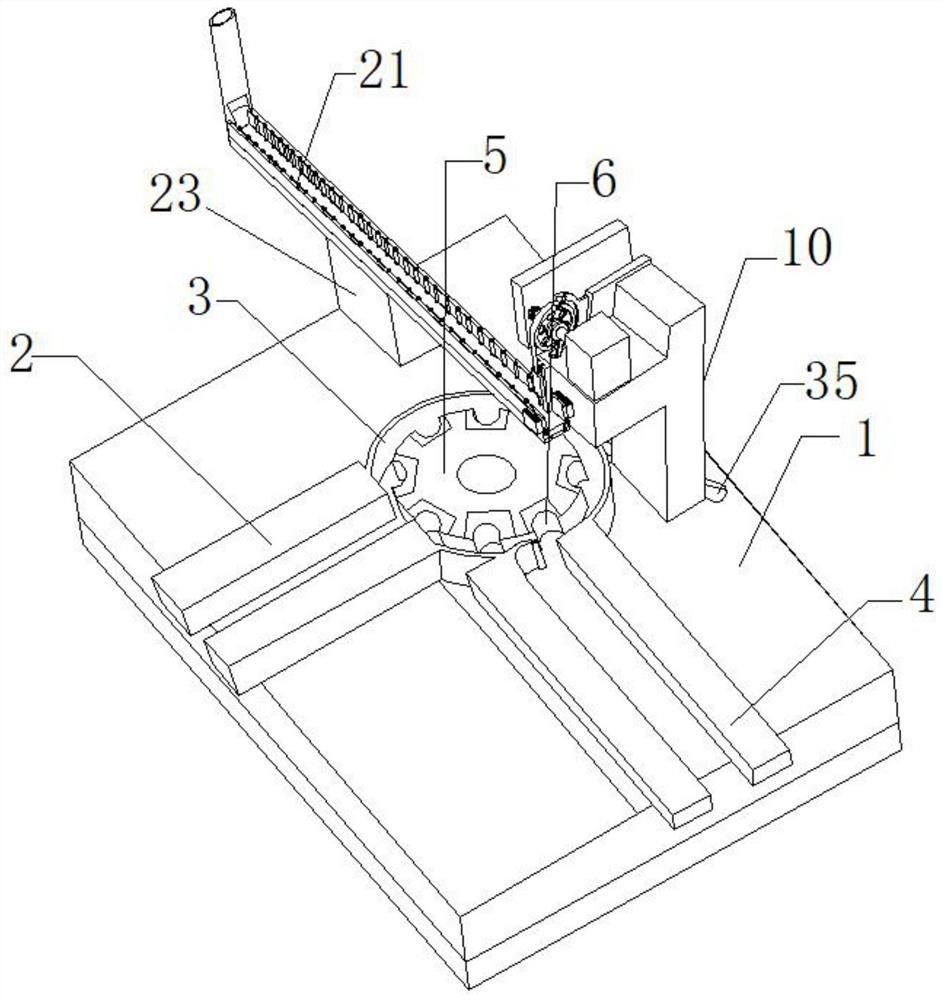
[0027] The following will clearly and completely describe the technical solutions in the embodiments of the present invention with reference to the accompanying drawings in the embodiments of the present invention. Obviously, the described embodiments are only some, not all, embodiments of the present invention. All other embodiments obtained by persons of ordinary skill in the art based on the embodiments of the present invention belong to the protection scope of the present invention.

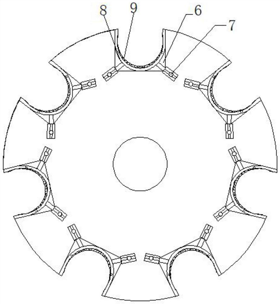
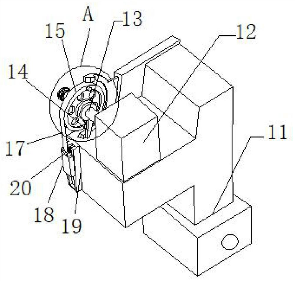
[0028] According to an embodiment of the present invention, a bottle cap piston capping device for chemical reagent bottles is provided, such as Figure 1 to Figure 7 As shown, among them,

[0029] A bottle cap piston capping device for chemical reagent bottles, comprising an equipment base 1, one end of the top of the equipment base 1 is fixedly equipped with a reagent bottle conveyor belt-2, and the outlet of the reagent bottle conveyor belt-2 is connected to the circle The inlet of the ci...


PUM


Abstract

The invention discloses a piston cap rolling device for a bottle cap of a chemical reagent bottle. The piston cap rolling device comprises an equipment base, wherein reagent bottle conveying belts I are fixedly mounted at one end of the top of the equipment base, outlets of the reagent bottle conveying belts I are fixedly connected with an inlet of a circular channel, and reagent bottle conveying belts II are connected to an outlet of the circular channel; and a strip disc is arranged in the center of the circular channel, a bearing seat is arranged at the top of the equipment base, a rotating rod is movably mounted in the bearing seat, one end of the rotating rod is fixedly connected with the bottom of the strip disc, the other end of the rotating rod is fixedly connected with a motor through a coupler, and the motor is fixedly mounted inside the equipment base. According to the piston cap rolling device, the piston covers of various types can be adapted through debugging an adjusting frame, the adaptation performance is high, excessive complex debugging does not need to be performed on the device before use, operation is easy and easy to understand, the device is convenient to control, and the cost is low.

Description

technical field [0001] The invention relates to the field of bottle cap stoppering, in particular to a bottle cap piston capping device for chemical reagent bottles. Background technique [0002] Piston capping machines crimp piston caps into bottle mouths, used in most chemical processing, filling machine processing, pharmaceutical factories, etc. At present, the existing piston cap capping devices generally use pneumatic capping, but this pneumatic capping requires adding a pneumatic booster device on the piston to connect the pipeline to the external gas cylinder device, through instantaneous pressurization The method of sealing the piston cap on the mouth of the chemical reagent bottle, but this method has a large equipment, takes up a large space and has high cost, and it is not suitable for small processing plants. In addition, the existing piston capping machine At the same time of capping, the chemical reagent bottle needs to be put into the conveying channel to be ...

Claims


Application Information

Patent Timeline
Patent Type & Authority Applications(China)
IPC IPC(8): B67B1/08B67B1/00B67B3/12
CPCB67B1/005B67B1/08B67B3/12
Inventor 不公告发明人
Owner 张雪莉
Learn More