Dyeing device for knitwear processing

A technology for needled textiles and dyeing devices, which is applied in the direction of textiles and papermaking, textile material processing, and textile material drums, etc. It can solve the problems of poor dyeing effect of needled textiles and the inability to guarantee dyeing uniformity, and achieve the goal of improving dyeing efficiency. Effect

Inactive Publication Date: 2021-04-06
苏州开江纺织品有限公司
View PDF0 Cites 0 Cited by
  • Summary
  • Abstract
  • Description
  • Claims
  • Application Information

AI Technical Summary

Problems solved by technology

[0003] At present, needled textiles need to be dyed after the processing is completed. In the prior art, the dyeing of needled textiles mostly uses the pump body to spray the dye on the surface of the needled textiles. The dyeing effect of needl

Method used


Image

  • Dyeing device for knitwear processing
  • Dyeing device for knitwear processing
  • Dyeing device for knitwear processing

Examples


Example Embodiment

[0025] Example 1

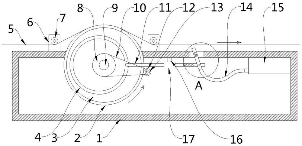
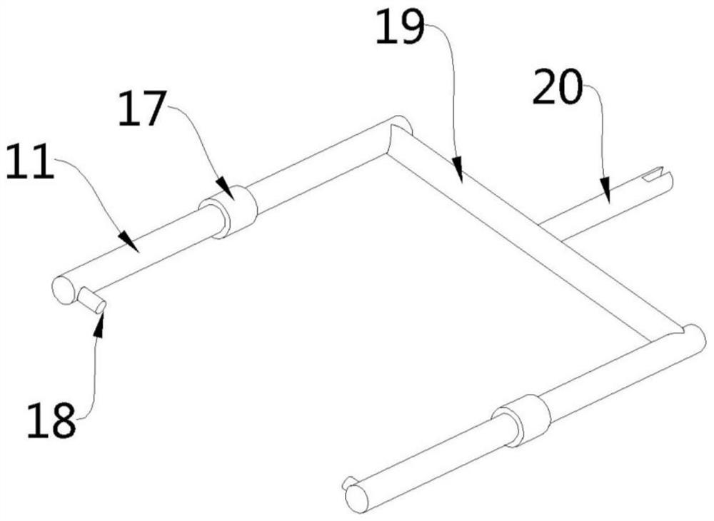
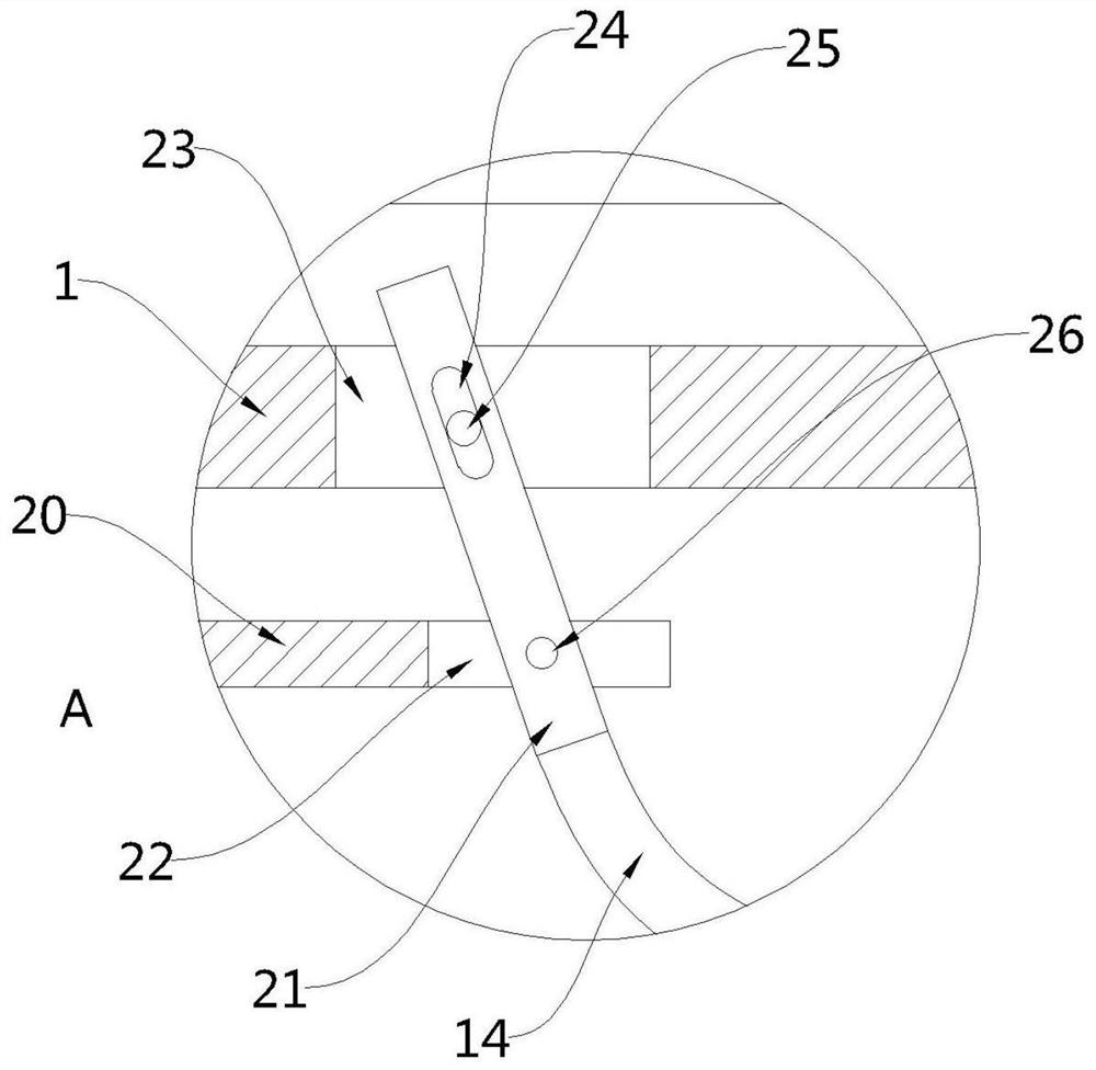
[0026] see Figure 1-3 , this embodiment provides a dyeing device for knitted textile processing, including a box body 1, the box body 1 contains dyeing agent, and a rotating roller 3 is rotated inside the box body 1, and the rotating roller 3 has a part located in the box body 1. Outside the upper part of the body 1, the middle part of the rotating roller 3 penetrates and is fixedly provided with a rotating shaft 9, one end of the rotating shaft 9 is connected with an external motor (not shown), the upper part of the box body 1 is provided with a through hole 23, and the interior of the through hole 23 A nozzle 21 is movably arranged, and an air supply assembly for introducing hot air into the nozzle 21 and a transmission for driving the nozzle 21 to swing back and forth along the through hole 23 are arranged inside the box 1 Specifically, the transmission assembly includes two sets of relatively distributed first push rods 11 , a cross rod 19 fixedly conn...

Example Embodiment

[0038] Example 2

[0039] see figure 1 , a dyeing device for needle textile processing. Compared with Embodiment 1, the upper part of the box body 1 is symmetrically distributed with two groups of brackets 6 with respect to the rollers 3, and one side of the brackets 6 of the two groups is A pressing roller 7 is arranged for rotation, and the horizontal plane of the bottom of the pressing roller 7 is located below the horizontal plane of the upper part of the turning roller 3 .

[0040] When the needled textile 5 moves horizontally along the upper part of the box body 1, two sets of pressure rollers 7 can be used to squeeze the needled textile 5, so as to squeeze the needled textile 5 on the upper part of the rotating roller 3, thereby increasing the contact between the needled textile 5 and the rotating roller 3. The contact effect between ensures that there is sufficient contact area between the needle textile 5 and the rotating roller 3, thereby ensuring the dyeing effect....


PUM


Abstract

The invention provides a dyeing device for knitwear processing, and belongs to the technical field of knitwear processing. The device comprises a box body; a coloring agent is contained in the box body; a rotating roller is rotatably arranged in the box body; one part of the rotating roller is positioned outside the upper portion of the box body; a rotating shaft is fixedly arranged in the middle of the rotating roller in a penetrating manner; one end of the rotating shaft is connected with an external motor; a through hole is formed in the upper portion of the box body; and a spraying pipe is movably arranged in the through hole. The dyeing device in the embodiment of the invention has the advantages of good knitwear and textile dyeing effect and uniform dyeing; the coloring agent in the box body is transferred to the bottom of the knitwear through the rotation of the rotating roller, so that the knitwear is colored; and the rotating roller can drive the spray pipe to reciprocate in the moving direction of the knitwear when rotating, so that the coloring agent attached to the bottom of the knitwear is effectively dried, and the dyeing efficiency of the knitwear is improved.

Description

technical field [0001] The invention belongs to the technical field of knitted textile processing, in particular to a dyeing device for knitted textile processing. Background technique [0002] Dyeing means dyeing color, also known as coloring, which refers to the use of chemical or other methods to affect the substance itself to color it. Under the conditions allowed by technology, dyeing can make objects show various colors that people need. Using colorful colors to decorate life, the method of dyeing has been around since ancient times and has continued to develop. [0003] At present, knitted textiles need to be dyed after processing. In the prior art, the dyeing of knitted textiles mostly uses a pump body to spray dyes on the surface of knitted textiles. This dyeing method has poor dyeing effect on knitted textiles. In addition, the dyeing uniformity cannot be guaranteed. Therefore, a dyeing device for knitted textile processing that can improve the dyeing effect and d...

Claims


Application Information

Patent Timeline
IPC IPC(8): D06B1/14D06B15/09D06B23/02D06B23/04
CPCD06B1/14D06B15/09D06B23/02D06B23/04
Inventor 顾忠
Owner 苏州开江纺织品有限公司
Why Eureka
Try Eureka