Drilling equipment for giant saw disc production

A technology of drilling equipment and sawing disc, which is applied in drilling/drilling equipment, boring/drilling, metal processing equipment, etc. The effect of efficiency

Inactive Publication Date: 2021-04-09
张开勇
View PDF4 Cites 2 Cited by
  • Summary
  • Abstract
  • Description
  • Claims
  • Application Information

AI Technical Summary

Problems solved by technology

[0005] In order to overcome the shortcomings of the deviation between the drill bit and the drilling position of the giant saw disc, and the time-consuming and labor-intensive situation, which reduces the work efficiency and increases the labor cost, the technical problem to be solved is: to provide an automatic drilling, the drilling position Precise and easy-to-use drilling equipment for the production of giant saw discs

Method used


Image

  • Drilling equipment for giant saw disc production
  • Drilling equipment for giant saw disc production
  • Drilling equipment for giant saw disc production

Examples


Embodiment 1

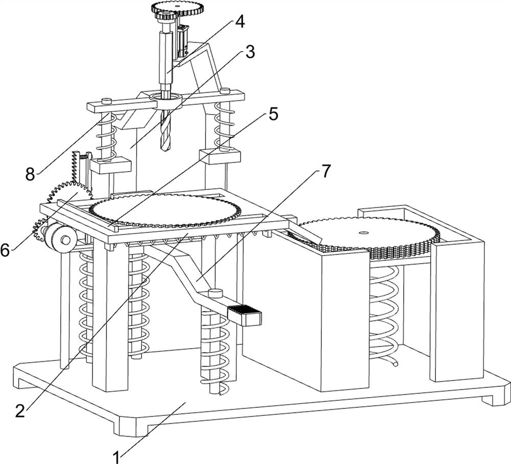
[0028] A drilling device for the production of giant saw discs, such as figure 1 , figure 2 and image 3 As shown, it includes a base 1, a workbench 2, a pressing assembly 3 and a drilling assembly 4. A drilling assembly 4 is provided on the side.

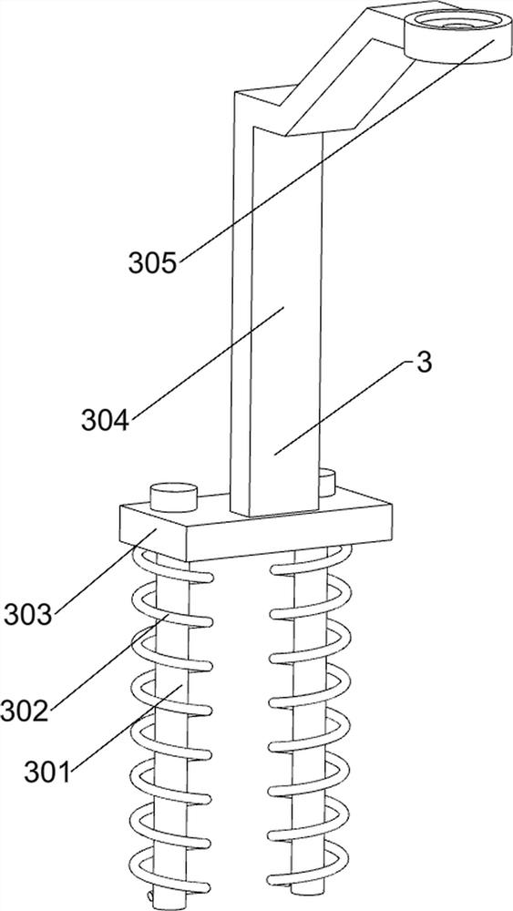
[0029] The pressing assembly 3 includes a first guide rod 301, a first spring 302, a first movable frame 303, a first connecting frame 304 and a first bearing 305, and the base 1 is provided with a first guide rod 301 on the left and right sides of the upper rear portion, The upper side of the first guide rod 301 is slidingly provided with a first movable frame 303, and two first springs 302 are connected between the first movable frame 303 and the base 1, and the first springs 302 are respectively sleeved on the first guide rod 301, The top of the first movable frame 303 is provided with a first connecting frame 304 , and the upper front side of the first connecting frame 304 is provided with a first bearing 305 .

[0030] Th...

Embodiment 2

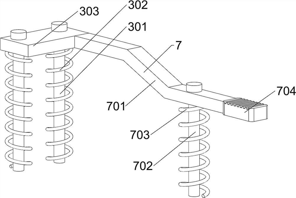
[0033] On the basis of Example 1, such as Figure 4 , Figure 5 , Figure 6 and Figure 7As shown, it also includes a discharge assembly 5, the discharge assembly 5 includes a push plate 501, a second spring 502, a first baffle 503, a second baffle 504, a movable plate 505 and a third spring 506, the workbench 2 There is a push plate 501 on the upper left sliding type, and a first baffle 503 is arranged symmetrically front and back on the lower side of the right part of the workbench 2, and a second spring 502 is connected between the lower side of the push plate 501 and the first baffle 503. Two second baffles 504 are arranged on the right side, and a movable plate 505 is slidably disposed between the upper sides of the second baffles 504 , and a third spring 506 is connected between the movable plate 505 and the base 1 .

[0034] After the giant saw disc is drilled, people push the push plate 501 to the right, the second spring 502 is compressed, and the push plate 501 wi...


PUM


Abstract

The invention relates to drilling equipment, in particular to drilling equipment for giant saw disc production. The technical problem to be solved is to provide the drilling equipment for giant saw disc production, which has the advantages of automatic drilling, accurate drilling position and convenience in use. According to the technical scheme, the drilling equipment for giant saw disc production comprises a base, a workbench, a pressing assembly and a drilling assembly; the workbench is arranged in the middle of the base; the pressing assembly is arranged on one side of the base; and the drilling assembly is arranged on the upper side of the pressing assembly. The drilling equipment for giant saw disc production has the beneficial effects that under the action of the pressing assembly and the drilling assembly, a giant saw disc is placed on the workbench, then a motor is started to drive a twist drill to rotate, then a first movable frame is pressed downwards to drive the twist drill to move downwards, and when the twist drill makes contact with the giant saw disc, the giant saw disc can be drilled; and the working efficiency of people is effectively improved.

Description

technical field [0001] The invention relates to a drilling device, in particular to a drilling device for producing a giant saw disc. Background technique [0002] A jumbo saw is the name given to thin circular knives used to cut solid materials. Saw blades can be divided into: diamond saw blades for stone cutting and high-speed steel saw blades for metal material cutting. [0003] After people manufacture the giant saw disc, in order to make it more convenient to use, they will drill holes in the center of the saw disc so that the giant saw disc can be installed on the machine. Align the center of the round block, and pull the drill bit down by the arm to complete the drilling work. This operation may cause deviations between the drill bit and the giant saw disc drilling position, and cause time-consuming and labor-intensive situations that reduce work efficiency and increase labor costs. . [0004] Therefore, it is particularly necessary to design a kind of automatic dr...

Claims


Application Information

Patent Timeline
Patent Type & Authority Applications(China)
IPC IPC(8): B23B41/00B23B47/06B23B47/30B23Q3/00B23Q7/00
CPCB23B41/00B23B47/30B23Q3/00B23Q7/00B23Q5/10B23Q2703/10
Inventor 张开勇
Owner 张开勇
Why Eureka
Try Eureka