Surface treatment equipment with scrap collecting function for bearing production

A technology for bearing production and surface treatment, applied in metal processing equipment, grinding/polishing equipment, manufacturing tools, etc., can solve the problems of reducing bearing accuracy, rough workpiece surface, large workload, etc., to improve the scope of application, improve processing The effect of precision and improved stability

Inactive Publication Date: 2021-04-09
汪庆文
View PDF18 Cites 4 Cited by
  • Summary
  • Abstract
  • Description
  • Claims
  • Application Information

AI Technical Summary

Problems solved by technology

[0003] The traditional bearing processing method mainly uses a lathe to process the surface of the bearing inner ring and the bearing outer ring, and then manually grinds the bearing surface. However, on the one hand, the manual grinding method has a large workload; Vibration is prone to occur, which makes the working process more unstable, thereby easily reducing the precision of bearing grinding, and the surface roughness of the bearing may not meet the standard; in addition, during the grinding process, abrasive grains are often not processed in time, and are caught between the workpiece and the grinding wheel. Occasionally, roughening occurs on the surface of the workpiece, causing irreversible damage and affecting the grinding effect

Method used


Image

  • Surface treatment equipment with scrap collecting function for bearing production
  • Surface treatment equipment with scrap collecting function for bearing production
  • Surface treatment equipment with scrap collecting function for bearing production

Examples


Embodiment 1

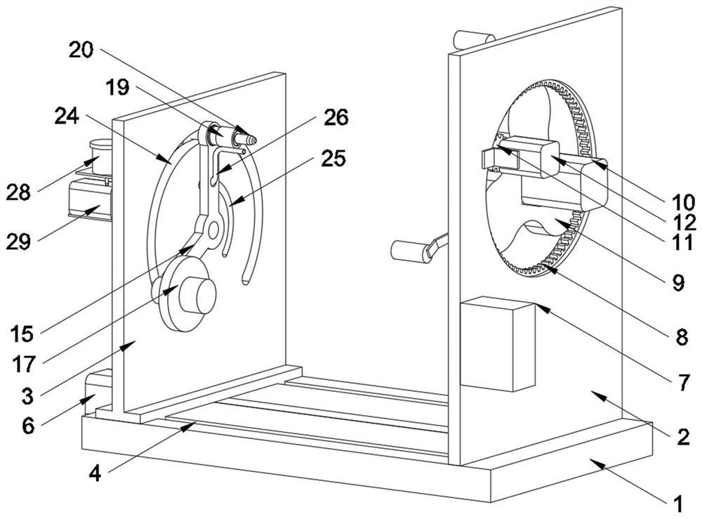
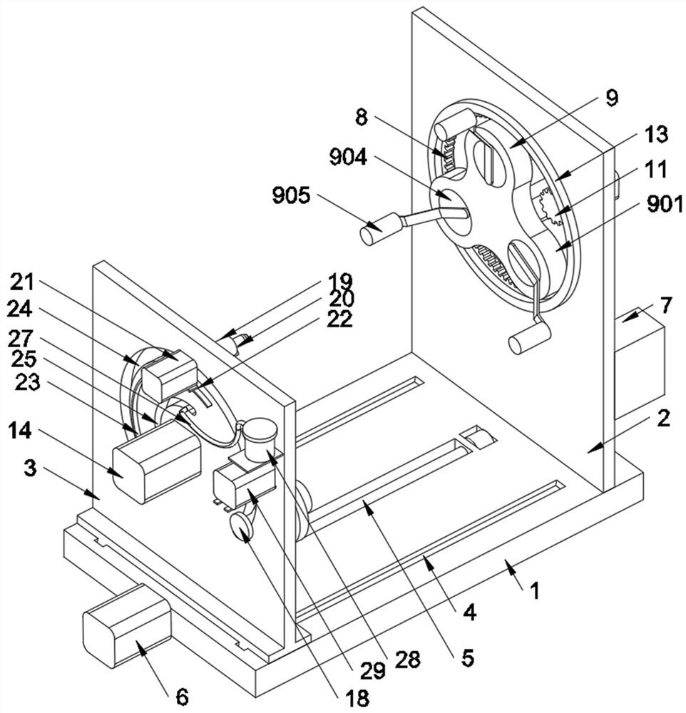
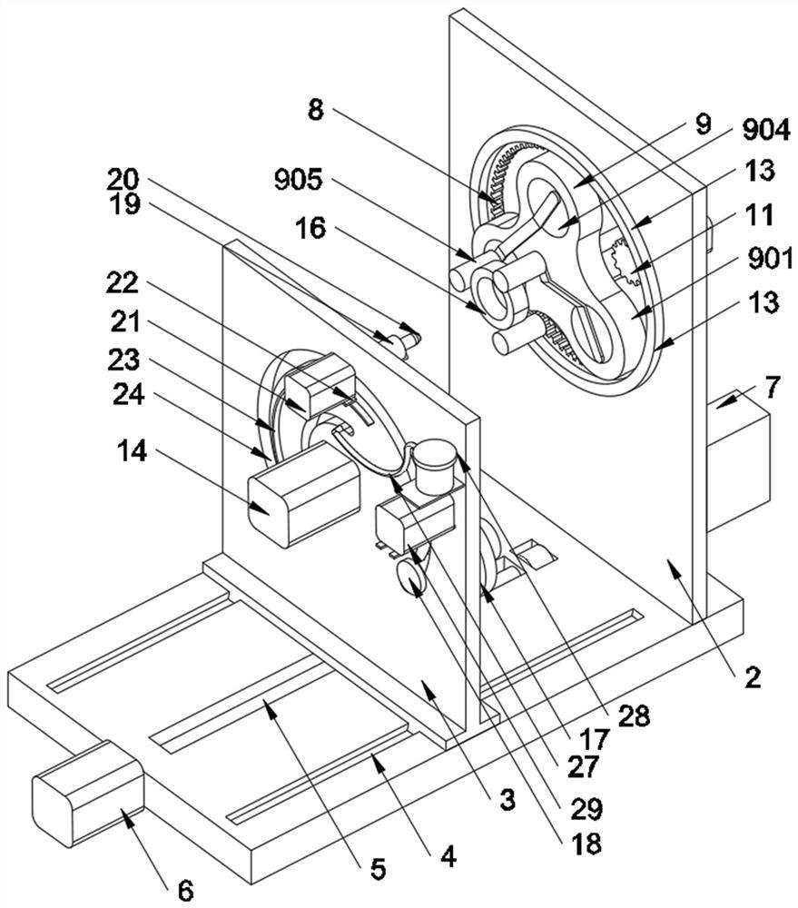
[0024] see Figure 1-Figure 5, the present invention provides the following technical solutions: a kind of surface treatment equipment with debris collection function for bearing production, including a workbench 1, the right end of the workbench 1 is fixedly installed with a right vertical plate 2, and the right vertical plate 2. The top surface of the workbench 1 on the left is provided with a dovetail groove 4 for slidingly installing the left vertical plate 3. The bottom of the left vertical plate 3 is connected with a ball screw 5, and one end of the ball screw 5 is fixed to connect the wire. The output shaft of the bar motor 6, the upper side of the right vertical plate 2 is provided with a groove for rotating and installing the inner gear ring 8, and the inner side of the inner gear ring 8 is meshed and connected with the drive gear fixedly installed on the output shaft of the drive motor 12 11. The left side of the internal gear ring 8 is fixedly connected to the side ...


PUM


Abstract

The invention belongs to the technical field of bearing surface treatment equipment, and particularly relates to surface treatment equipment with a scrap collecting function for bearing production. The surface treatment equipment comprises a worktable, a right vertical plate is mounted at the right end of the worktable, a dovetail groove for slidably mounting a left vertical plate is formed in the worktable on the left side of the right vertical plate, and a ball screw is in transmission connection with the bottom of the left vertical plate; a driving gear is in meshed connection with the inner side of an inner gear ring rotatably mounted on the right vertical plate, the left side of the inner gear ring is fixedly connected with a three-jaw clamping jaw, an output shaft of a feeding motor installed on the left vertical plate is fixedly connected with a rotating frame, a feeding sleeve rod and a spring chuck are installed at the two ends of the rotating frame, a grinding wheel is clamped at the head end of the spring chuck, and the tail end of the spring chuck is connected with an output shaft of a grinding motor; and a scrap pumping pipe installed on the rotating frame is connected with a vacuum pump through a hose and a dust filtering box, the three-jaw clamping jaw can conduct self-centering clamping on bearings of different sizes and enables the bearings which rotate slowly to be evenly ground by the grinding wheel which is fed in a rotating mode, the scrap pumping pipe can suck and remove abrasive particles generated by grinding, and the galling phenomenon is avoided.

Description

technical field [0001] The invention belongs to the technical field of bearing surface treatment equipment, and in particular relates to a surface treatment equipment used for bearing production and having the function of collecting debris. Background technique [0002] Bearings are generally composed of outer rings, inner rings, rolling elements and retaining brackets, which are usually called four major parts. Strictly speaking, they are composed of six major parts: outer rings, inner rings, rolling elements, cages, seals, and lubricating oil; Due to the working characteristics of the bearing, the surface treatment of the inner ring of the bearing requires higher machining accuracy and requirements than the surface treatment of the outer ring. When the surface roughness of the bearing does not meet the standard, the service life of the bearing will be seriously reduced. [0003] The traditional bearing processing method mainly uses a lathe to process the surface of the bea...

Claims


Application Information

Patent Timeline
Patent Type & Authority Applications(China)
IPC IPC(8): B24B5/10B24B5/35B24B41/06B24B41/02B24B47/12B24B55/06B24B47/04
CPCB24B5/10B24B5/355B24B41/02B24B41/062B24B47/04B24B47/12B24B55/06
Inventor 汪庆文
Owner 汪庆文
Why Eureka
Try Eureka