Machining system and method for cooling, heating and power cogeneration combined supply part of diesel engine

A technology of combined cooling, heating and power generation and processing systems, which is applied to the parts of grinding machine tools, metal processing equipment, manufacturing tools, etc., and can solve problems such as reducing work efficiency, reducing the service life of diesel engines, and easy damage to flywheels

Active Publication Date: 2021-04-09
东方电气(成都)工程设计咨询有限公司
View PDF16 Cites 0 Cited by
  • Summary
  • Abstract
  • Description
  • Claims
  • Application Information

AI Technical Summary

Problems solved by technology

The kinetic energy of the diesel engine can be stored when it rotates at high speed. The flywheel of some diesel engines rotates at high speed, so the texture of the flywheel needs to be very well-proportioned. The body causes damage, reducing the service life of the diesel engine;
[0006] The flywheel requires manual participation of the staff during processing. The weight and volume of the flywheel are relatively large, so the staff are easy to be injured when handling the flywheel of the diesel engine. It is dangerous, and manual processing also reduces work efficiency and increases labor costs, and the texture of the flywheel is very hard, which requires a grinding process, and a lot of metal debris and smoke will be generated when the flywheel is polished

Method used


Image

  • Machining system and method for cooling, heating and power cogeneration combined supply part of diesel engine
  • Machining system and method for cooling, heating and power cogeneration combined supply part of diesel engine
  • Machining system and method for cooling, heating and power cogeneration combined supply part of diesel engine

Examples


Embodiment Construction

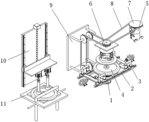
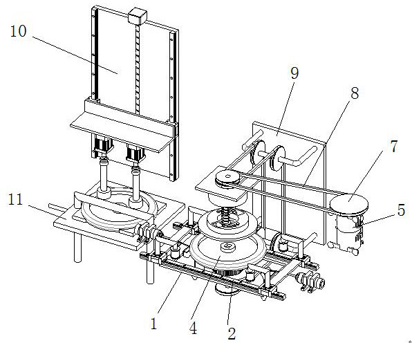
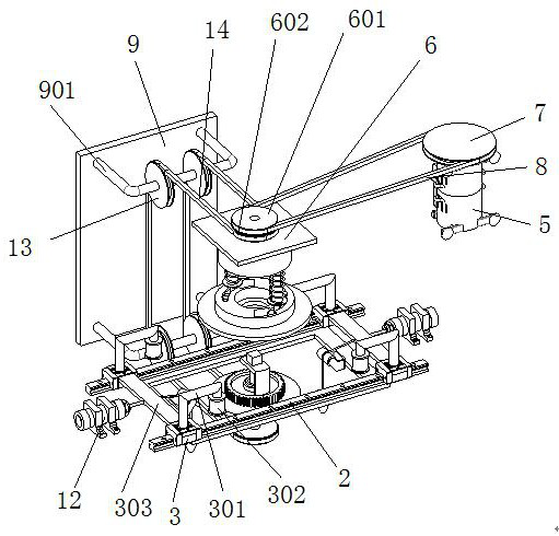
[0036] In order to make the object, technical solution and advantages of the present invention clearer, the present invention will be further described in detail below in conjunction with the accompanying drawings and embodiments. It should be understood that the specific embodiments described here are only used to explain the present invention, not to limit the present invention.

[0037] In describing the present invention, it should be understood that the terms "longitudinal", "transverse", "upper", "lower", "front", "rear", "left", "right", "vertical", The orientations or positional relationships indicated by "horizontal", "top", "bottom", "inner", "outer", etc. are based on the orientations or positional relationships shown in the drawings, and are only for the convenience of describing the present invention, rather than indicating or It should not be construed as limiting the invention by implying that a referenced device or element must have a particular orientation, be...


PUM


Abstract

The invention discloses a machining system and method for a cooling, heating and power cogeneration combined supply part of a diesel engine, and belongs to the field of flywheel machining. The method comprises the following steps that 1, the machining system for the cooling, heating and power cogeneration combined supply part of the diesel engine is provided; 2, a square hole in the middle of a to-be-machined flywheel is aligned with a locking square block to be inserted, the top face of the locking square block does not exceed the top face of the square hole, and therefore the to-be-machined flywheel and a bearing wheel disc can synchronously rotate; and 3, when sliding blocks slide on a guide rail, a tension wire and a lead block in the middle of a connecting plate apply pressure to the sliding blocks towards the middle, and groove wheels at the ends of the four sliding blocks are folded towards the middle so as to clamp the periphery of the to-be-machined flywheel. By means of the machining system and method, the flywheel can be automatically machined, the machining efficiency of the flywheel is high, and the flywheel is safe to the human body.

Description

technical field [0001] The invention relates to the field of flywheel processing and manufacturing, in particular to a processing system and method for components used in combined cooling, heating and power generation of diesel engines. Background technique [0002] Distributed Energy System (Distributed Energy System) is already a mature energy comprehensive utilization technology in many countries and regions. It is close to users, cascade utilization, high efficiency of primary energy utilization, environment-friendly, safe and reliable energy supply, etc. It has received wide attention and favor from governments and business circles of various countries. There are many forms of distributed energy systems, and the combined cooling, heating and power (CCHP) of regional or building groups or independent large and medium-sized buildings is one of the very important ways. [0003] The gas-fired combined cooling, heating and power system is based on the concept of cascade uti...

Claims


Application Information

Patent Timeline
IPC IPC(8): B24B7/04B24B7/16B24B5/48B24B27/00B24B41/06B24B47/12B24B47/20
CPCB24B7/04B24B7/16B24B5/48B24B27/0023B24B27/0076B24B41/067B24B47/20B24B47/12
Inventor 黄松刘泽鑫胡斌
Owner 东方电气(成都)工程设计咨询有限公司
Why Eureka
Try Eureka