
Three-dimensional pattern sponge cutting machine

A sponge cutting machine and pattern technology, applied in metal processing and other directions, can solve the problems of complex and troublesome installation structures, and achieve the effect of increasing production efficiency

Pending Publication Date: 2021-04-09
南通恒康数控机械股份有限公司
View PDF1 Cites 2 Cited by
  • Summary
  • Abstract
  • Description
  • Claims
  • Application Information

AI Technical Summary

Problems solved by technology

In such a processing mode, the style of the shape will be limited by the size and space of the pressure roller, and generally speaking, in consideration of various conditions such as manufacturing cost and processing difficulty, the same pressure roller There will only be one shape, so when it is necessary to cut three-dimensional figures of different shapes, it is very troublesome to replace the upper and lower pressure rollers, and the installation structure of the upper and lower pressure rollers is relatively complicated. It is troublesome to replace the pressure roller

Method used


Image

  • Three-dimensional pattern sponge cutting machine
  • Three-dimensional pattern sponge cutting machine
  • Three-dimensional pattern sponge cutting machine

Examples


Embodiment Construction

[0028] The following examples can enable those skilled in the art to understand the present invention more comprehensively, but the present invention is not limited to the scope of the described examples.

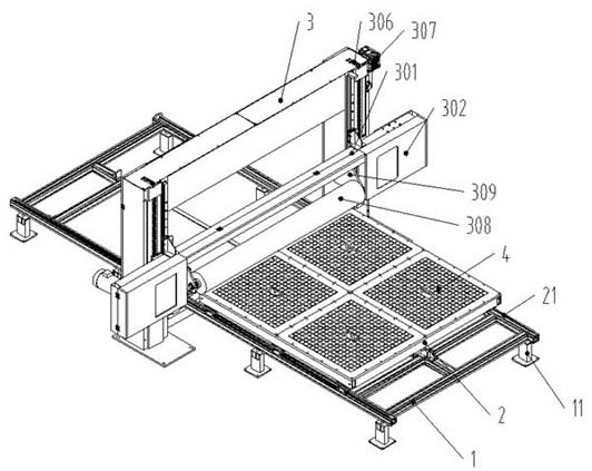
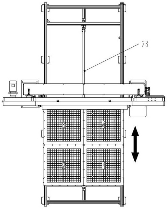
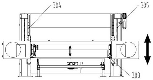
[0029] Such as Figure 1-Figure 6 A three-dimensional pattern sponge cutting machine shown, including

[0030] A processing support 1, the processing support 1 is a rectangular frame structure composed of several horizontal bars and vertical bars, and several supporting feet 11 are connected to the bottom end of the processing support 1.

[0031] A conveying unit installed on the processing support 1, the conveying unit includes a conveying platform 2, the conveying platform 2 is a rectangular plate, and the conveying platform 2 is driven by a conveying drive mechanism to reciprocate along the long axis of the processing support 1.

[0032] The conveying drive mechanism is as follows: a horizontal translation guide rail 21 is installed on both sides of the processing suppo...


PUM


Abstract

The invention relates to a three-dimensional pattern sponge cutting machine. The three-dimensional pattern sponge cutting machine comprises a machining support, a conveying platform installed on the machining support, a portal frame stretching across the machining support, and a modeling unit. A cutting support is installed on the portal frame, cutter boxes are further installed on the two sides, in the horizontal direction, of the cutting support, and an annular cutter belt is arranged between the two cutter boxes. The modeling unit comprises a modeling plate installed on the conveying platform and a pressing roller installed on the cutting support, the modeling plate is provided with modeling cavities sunken towards the interior of the modeling plate, and the modeling plate is fixed on the conveying platform through bolts. The three-dimensional pattern sponge cutting machine has the advantages that by designing the modeling unit, a three-dimensional pattern into which sponge is to be cut is formed through cooperation of the pressing roller and the modeling plate; by designing the modeling cavities in the modeling plate, the problem that modeling design on the pressing roller is limited by the size, the space and the like is solved; and the modeling cavities can be designed to be more diversified, and the problem of product simplicity is solved.

Description

technical field [0001] The invention relates to the field of sponge cutting, in particular to a three-dimensional flower-shaped sponge cutting machine. Background technique [0002] A sponge is a porous material that absorbs water well and can be used to clean items. It is usually formed by mixing foaming resin, foaming aids and binder resins. The foaming machine is a device for making sponges. The air is introduced into the aqueous solution of the foaming agent to disperse evenly through the mechanical stirring of the foaming machine. Make the foaming agent in the liquid phase and the air in the gas phase have as large a contact surface as possible and react to form bubbles one by one to form a sponge. After the sponge is generated as a whole, it needs to be cut into different sizes according to different needs. [0003] At present, when cutting the three-dimensional graphics of the sponge, a profile cutting machine is usually used. However, because the general profile cu...

Claims


Application Information

Patent Timeline
IPC IPC(8): B26D1/02B26D7/02B26D7/06B26D7/26
CPCB26D1/02B26D7/02B26D7/06B26D7/2628
Inventor 倪张根吴晓宇袁海峰
Owner 南通恒康数控机械股份有限公司
Learn More