Vehicle spiral progressive cutting impact energy dissipation method and device
An impact energy, spiral technology, applied in the direction of railway vehicle wheel guard/buffer, transportation and packaging, railway car body parts, etc., can solve the problems of low energy absorption efficiency, small energy absorption, etc. energy efficiency, increase energy absorption stability, and improve the effect of cutting stroke
- Summary
- Abstract
- Description
- Claims
- Application Information
AI Technical Summary
Problems solved by technology
Method used
Image
Examples
Embodiment 1
[0056] A spiral progressive cutting impact energy dissipation method for a vehicle according to an embodiment of the present invention, which combines a crushing energy-absorbing structure with a spiral cutting energy-absorbing structure, and adopts two methods of crushing energy absorption and spiral cutting energy absorption jointly absorb the kinetic energy of the collision. The design method of the present invention combines the crushing energy-absorbing method and the spiral cutting energy-absorbing method, and transforms the single axial translation of the traditional cutting energy-absorbing device into an axial and circumferential helical combined movement, which improves the Energy absorption and energy absorption rate of the device.
[0057] Furthermore, the helical cutting energy-absorbing structure is sleeved inside the crushing-type energy-absorbing structure to provide guiding support for the crushing-type energy-absorbing structure and reduce the overall size of...
Embodiment 2
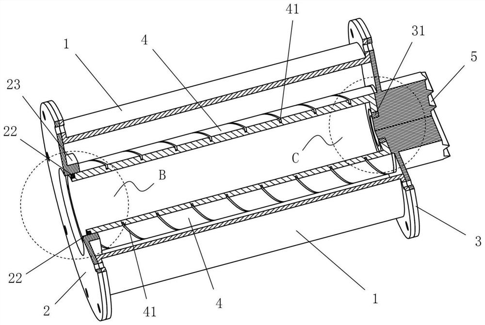
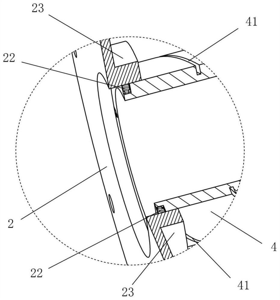
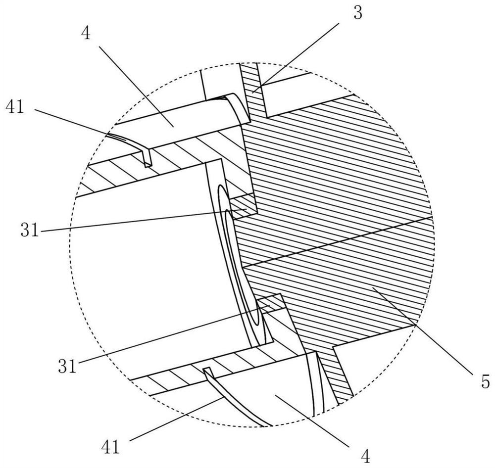
[0060] see Figure 1 to Figure 18 , a vehicle spiral progressive cutting impact energy dissipation device according to an embodiment of the present invention, the energy dissipation device mainly includes a crushing energy-absorbing sleeve 1, a rear end plate 2, a front end plate 3 and a cutting energy-absorbing mandrel 4 . Among them, the rear end plate 2 is installed on one end of the crushing type energy-absorbing sleeve 1, and the front end plate 3 is installed on the end of the crushing type energy-absorbing sleeve 1 opposite to the rear end plate 2; A through hole 21, a cutting tool 22 is installed on the inner wall of the through hole 21; the cutting energy-absorbing mandrel 4 is arranged in the inner cavity of the crushing energy-absorbing sleeve 1, and one end of the cutting energy-absorbing mandrel 4 is rotatable The other end of the cutting energy-absorbing mandrel 4 is rotatably installed on the inner side of the front end plate 3, and the outer wall of the cuttin...
Embodiment 3
[0078] see Figure 19 to Figure 20 , Another embodiment of the vehicle spiral progressive cutting impact energy dissipating device of the present invention, the main structure of the energy dissipating device is the same as that of Embodiment 2, and will not be repeated here. Compared with Embodiment 2, the main difference of the energy dissipating device of this embodiment is that on the inner wall of the through hole 21 and the inner wall of the annular rib 23, multi-layer cutting tools 22 are arranged in the axial direction, each Each layer comprises a plurality of cutting knives 22 uniformly distributed along the circumferential direction, and the cutting knives 22 of different layers are in a helical arrangement consistent with the helical guide groove 41 (such as Figure 20 , the same dotted line represents the cutting tools 22 of the same layer). A cutting tool 22 in each layer is accommodated in the same spiral guide groove 41; The width of 221 increases step by step...
PUM
 Abstract
Description
Claims
Application Information
 - R&D
- Intellectual Property
- Life Sciences
- Materials
- Tech Scout
- Unparalleled Data Quality
- Higher Quality Content
- 60% Fewer Hallucinations
Browse by: Latest US Patents, China's latest patents, Technical Efficacy Thesaurus, Application Domain, Technology Topic, Popular Technical Reports.
© 2025 PatSnap. All rights reserved.Legal|Privacy policy|Modern Slavery Act Transparency Statement|Sitemap|About US| Contact US: help@patsnap.com


