
Hybrid laminar flow wing air suction energy loss engineering calculation method

A technology of energy loss and engineering calculation, applied in the direction of air flow, aircraft parts, aircraft control, etc. that affects the surface of the aircraft, it can solve the problems such as the inability to carry out the design of aircraft performance indicators, the lack of them, and achieve the effect of fine and comprehensive calculation model.

Active Publication Date: 2021-04-09
XIAN AIRCRAFT DESIGN INST OF AVIATION IND OF CHINA
View PDF8 Cites 4 Cited by
  • Summary
  • Abstract
  • Description
  • Claims
  • Application Information

AI Technical Summary

Problems solved by technology

At present, most of the energy loss data of hybrid laminar flow wing aircraft comes from flight test data. Due to the lack of calculation methods for energy loss of suction, it is impossible to carry out the performance index design, thrust-to-weight ratio design, wing airfoil and Planar parameter optimization design

Method used


Image

  • Hybrid laminar flow wing air suction energy loss engineering calculation method
  • Hybrid laminar flow wing air suction energy loss engineering calculation method
  • Hybrid laminar flow wing air suction energy loss engineering calculation method

Examples


Embodiment Construction

[0040] This part is the embodiment of the present invention, which is used to explain and illustrate the technical solution of the present invention.

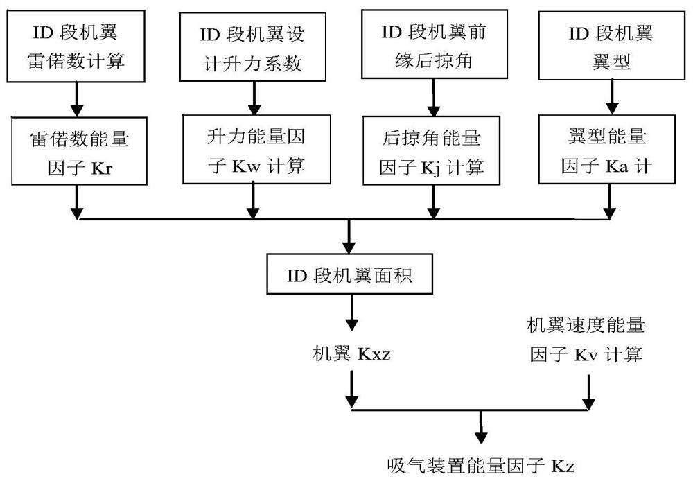
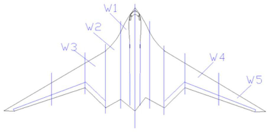
[0041] An engineering calculation method for air intake energy loss of a mixed laminar flow wing. According to CFD calculation data, wind tunnel test data and flight test data analysis, the Rero number REN, lift coefficient CL, wing leading edge sweep Angle Λw and cruising Mach number are the engineering calculation function of the energy loss factor of the wing suction device; taking the position of the upper and lower wing layer flow transition obtained from the X21 flight test as a reference, the eN wing boundary layer flow transition considering suction is used The position calculation method calculates the energy loss factor produced by the mass of the airfoil, and finally obtains the energy loss factor of the wing suction device of the whole aircraft by summing the area integral of the energy loss factor of the wing span t...


PUM


Abstract

The invention discloses a hybrid laminar flow wing air suction energy loss engineering calculation method, which comprises the following steps: according to CFD calculation data, wind tunnel test data and flight test data analysis, respectively fitting a wing air suction device energy loss factor calculation function taking a Rayleigh number REN, a lift coefficient CL, a wing front edge sweepback angle lambda w and a cruise Mach number as independent variables; calculating an energy loss factor generated by airfoil mass by using an eN airfoil boundary layer-by-layer transition position calculation method considering air suction by taking the upper and lower airfoil layer-by-layer transition positions obtained by the X21 flight test as a reference, and finally, calculating the total area of the energy loss factor generated by the airfoil mass by summing the area integral of the energy loss factor of each airfoil section in the airfoil span direction, and obtaining the energy loss factor of the wing air suction device of the whole aircraft. The method provided by the invention is suitable for demonstrating the power demand of the air suction device at the front edge of the hybrid laminar flow wing with complex configuration, and provides technical support for the thrust-weight ratio design of a hybrid laminar flow control technology aircraft and the optimal design of the wing configuration based on the air suction system pipeline design of power distribution optimization.

Description

technical field [0001] The invention belongs to the technical field of aviation vehicle design, and relates to a calculation method for wing suction energy loss of a transport aircraft, in particular to an engineering calculation method for mixed laminar flow wing suction energy loss. Background technique [0002] The natural laminar flow technology has strict requirements on the flight environment and wing configuration, and is only suitable for small aircraft with a speed of no higher than 0.7 Ma; the suction device of the full laminar flow control technology is complicated, and the energy loss is large; The air energy consumption is small, and the drag reduction effect is obvious. It is one of the best drag reduction technologies with application prospects. The energy loss of wing suction device is sensitive to the influence of aircraft performance, so accurate calculation of its energy loss is a key technology to evaluate the performance of mixed laminar flow control win...

Claims


Application Information

Patent Timeline
Patent Type & Authority Applications(China)
IPC IPC(8): B64F5/00B64C3/36B64C21/06
CPCB64F5/00B64C3/36B64C21/06Y02T90/00
Inventor 张声伟张健
Owner XIAN AIRCRAFT DESIGN INST OF AVIATION IND OF CHINA
Learn More