
Point laying periodic cushion layer vibration reduction ballast bed

The technology of cushion and ballast bed is applied in the field of point laying period cushion vibration damping ballast bed, which can solve the problems of abnormal damage of equipment and parts, increase the maintenance and repair workload of the wheel-rail system, and increase the vibration quality, etc., so as to save energy. The effect of reducing the cost of vibration reduction, reducing the burden on the track system, and improving the low-frequency vibration isolation effect

Active Publication Date: 2021-04-09
CHINA RAILWAY DESIGN GRP CO LTD
View PDF7 Cites 0 Cited by
  • Summary
  • Abstract
  • Description
  • Claims
  • Application Information

AI Technical Summary

Problems solved by technology

[0002] At present, the rail vibration reduction measures widely used in the environmental vibration control of rail transit have exposed the following problems: (1) The principle of existing rail vibration reduction is to reduce the support stiffness or increase the vibration mass, and excessive vibration reduction or improper vibration reduction may cause wheel vibration. The abnormal wear of the rails will cause rapid and abnormal damage to equipment and parts, increase the workload of maintenance and repair of the wheel-rail system, and even affect the stability and safety of driving; (2) The vibration reduction section is long and the investment is high. Take the 30km subway as an example, the cost increase caused by track vibration reduction may reach 200 million yuan; (3) Passenger ride comfort is seriously damaged in the section paved with steel spring floating slabs
[0004] At present, there is no report on the periodical design of the structures involved in rail transit to realize the active regulation of vibration by using the forbidden band characteristics of periodic structures.

Method used


Image

  • Point laying periodic cushion layer vibration reduction ballast bed
  • Point laying periodic cushion layer vibration reduction ballast bed
  • Point laying periodic cushion layer vibration reduction ballast bed

Examples


Embodiment 1

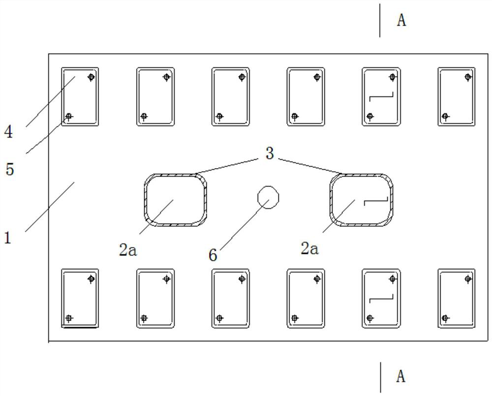
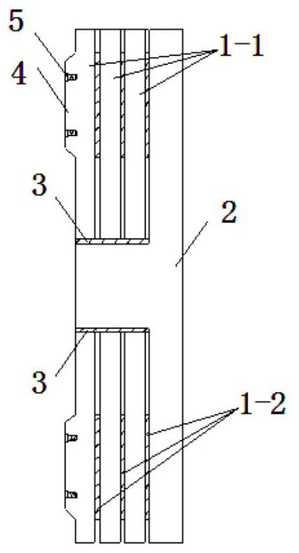
[0066]The concrete plate 1-1 and the periodic pad layer 1-2 have a width of 2.2 M, and the concrete plate 1-1 thickness is 0.1m, and the cycle pad layer 1-2 takes the rubber material, the thickness is 0.01m, and the width is 0.2m. , The length of 0.2m, Embodiment 1, and Embodiment 2, is disposed below the carrier station 4; Embodiment 3 and Embodiment 4, in the middle of the two adjacent bond tables 4 is disposed. The concrete panel 1-1 is repeated by the cycle pad layer 1-2, and each is repeated 3 times, and a periodic composite ribbon 1 having a thickness of 0.33 mm is constituted. The concrete substrate and restricted structure 2 has a thickness of 0.15 m, a projection height of 0.33 m, and the discrete projections are 0.4m × 0.5 m (0.5m is the direction of the line along the line); In the second and fourth embodiments, the longitudinal section of the continuous projections is 0.33 m × 0.4 m (0.4m is the vertical line walking direction size). The elastic pad layer 3 is a rubber a...


PUM

PropertyMeasurementUnit
Thicknessaaaaaaaaaa

Abstract

The invention provides a point laying periodic cushion layer vibration reduction ballast bed which comprises a periodic composite ballast bed plate and a concrete base arranged below the periodic composite ballast bed plate, the periodic composite ballast bed plate and the concrete base are limited through a limiting structure, and relative displacement is prevented. The periodic composite roadbed bed plate is formed by alternately arranging and solidifying concrete slabs and periodic cushion layers from top to bottom, and the projections of the concrete slabs in the vertical direction completely coincide. Each concrete slab and the adjacent periodic cushion layer below the concrete slab form a basic unit, and the number of periodic repetitions of the basic units in the vertical direction is not less than 2; and the periodic cushion layer is formed by regularly and discretely distributing square cushion plates along the driving direction. Elastic wave forbidden bands are formed in the vertical direction, the transverse direction and the longitudinal direction of the vibration reduction ballast bed, propagation of vibration in the three directions can be effectively controlled, the forbidden band range can be actively adjusted by changing the geometric dimension of the structure and material composition, and adjustability is high.

Description

Technical field[0001]The present invention relates to the field of track traffic damping noise reduction, and more particularly to a dotting cycle cushion damping bed.Background technique[0002]At present, the rail transformation measures widely adopted by the rail transit environment have exposed the following issues: (1) The principle of existing track damping is to reduce the stiffness of the support or increase the quality of the vibration, and may cause the wheel. Tracks from rails, resulting in fast abnormal injuries of equipment and components, increase wheel rail system maintenance and maintenance work, and even affect the stability and safety of driving; (2) long, high investment, with a long investment 30km Metro as an example, the increase in cost increase can reach 200 million yuan; (3) The passenger ride of the steel spring floating plate is seriously damaged.[0003]Solid physics studies have found that the incident waves cannot be propagated in the periodic medium when t...

Claims


Application Information

Patent Timeline
IPC IPC(8): E01B3/28E01B19/00
CPCE01B3/28E01B19/00
Inventor 齐春雨姜博龙刘冀钊胡文林王少林何宾杨宝峰杨其振刘道通谭大正程保青徐彩彩韩朝霞
Owner CHINA RAILWAY DESIGN GRP CO LTD
Learn More