A flow channel adjustment structure and control method of a direct drive combined engine

A technology for adjusting structures and control methods, applied to machines/engines, mechanical equipment, gas turbine devices, etc., can solve problems such as difficult collaborative control, low operating efficiency, and complex mechanism systems, and achieve low collaborative control difficulty and high operating efficiency , the effect of high adjustment accuracy

Active Publication Date: 2021-11-19
HUAZHONG UNIV OF SCI & TECH
View PDF10 Cites 0 Cited by
  • Summary
  • Abstract
  • Description
  • Claims
  • Application Information

AI Technical Summary

Problems solved by technology

[0009] Aiming at the above defects or improvement needs of the prior art, the present invention provides a direct-drive combination engine channel adjustment structure and its control method, the purpose of which is to solve the complex mechanism system caused by the use of complex mechanical indirect transmission adjustment in the prior art. , low operating efficiency, and difficult technical problems in collaborative control

Method used


Image

  • A flow channel adjustment structure and control method of a direct drive combined engine
  • A flow channel adjustment structure and control method of a direct drive combined engine
  • A flow channel adjustment structure and control method of a direct drive combined engine

Examples


Embodiment 1

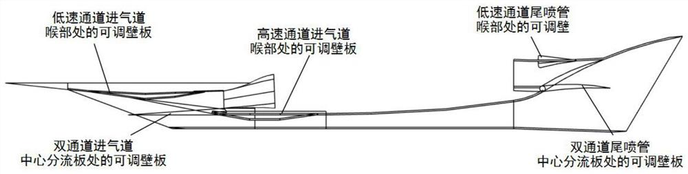
[0065] Such as figure 1 Shown is a typical Ma-6+ upper and lower parallel combined engine mechanism. The parallel combined engine realizes functions such as flow control, exhaust expansion ratio control, and mode conversion through the coordinated adjustment of the intake port, combustion chamber, and tail nozzle. The adjustable wall plate is designed according to the working conditions and adjustment requirements. Specifically, as shown in Table 1, the specific adjustment requirements of the flow passages at various parts of the engine and the corresponding motion forms of the adjustable wall plate are shown.

[0066] Table 1

[0067]

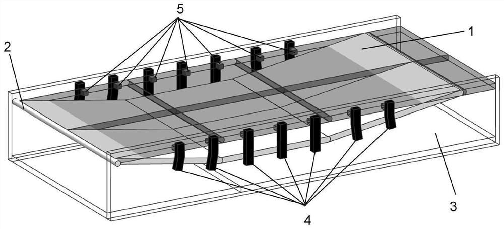
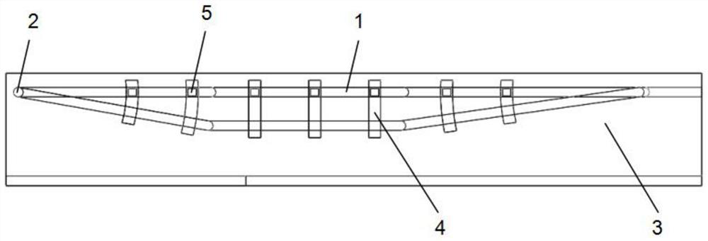
[0068] Specifically, as figure 2 The flow channel regulating structure at the inlet throat of the high-speed passage of the parallel combined engine shown above is described in detail as an example. image 3 shown.

[0069] Specifically, the flow channel adjustment structure at the throat of the air inlet of the high-speed passage incl...

Embodiment 2

[0089] A control method for directly driving the flow channel adjustment structure of a combined engine, taking the flow channel adjustment structure of the combined engine described in Embodiment 1 as an example, specifically includes the following steps:

[0090] S1. According to the current flight state and flight attitude of the aircraft, the current expected performance requirements of the engine and the operating parameters of the flow passage, calculate the flow passage area and flow passage ratio, thereby determining the flow passage profile;

[0091] Specifically, the flight state includes the Mach number and flight altitude of the aircraft; the flight attitude includes the flight pitch angle and attack angle of the aircraft; the performance of the engine includes: engine thrust, thrust gain, engine specific impulse and specific impulse gain; engine flow path operating parameters Including: the flow parameters, temperature, pressure and velocity of the working medium i...

Embodiment 3

[0113] A computer-readable storage medium, the computer-readable storage medium includes a stored computer program, wherein when the computer program is run by a processor, the device where the storage medium is located is controlled to execute the direct method provided by Embodiment 2 of the present invention A control method for driving a combination engine flow channel adjustment structure.

[0114] The relevant technical solutions are the same as those in Embodiment 2, and will not be repeated here.


PUM


Abstract

The invention discloses a direct-drive combined engine flow channel adjustment structure and a control method thereof, comprising a plurality of electromagnetic direct drive units; the electromagnetic direct drive unit includes a stator and a mover; each stator is embedded and installed inside the flow channel body, And symmetrically distributed on the two side walls of the flow channel body; each mover is embedded in the interior of the adjustable wall plate, and symmetrically distributed on both sides of the adjustable wall plate close to the flow channel body, corresponding to the position of the stator ; By adjusting the alternating current input at the stator, the adjustable wall plate is moved; the present invention adopts the distributed arrangement of multiple electromagnetic direct drive units, which can be carried out with the minimum energy consumption according to the real-time force conditions such as the internal pressure of the flow channel and frictional damping. Distributed direct drive force output, and a complete distributed control scheme, combined engine full-channel multi-component collaborative control process, high structural integration, simple system, greatly improved system operating efficiency, and reduced system structural quality costs.

Description

technical field [0001] The invention belongs to the field of aerospace engines, and more specifically relates to a direct-drive combined engine channel adjustment structure and a control method thereof. Background technique [0002] Future horizontal take-off and landing hypersonic vehicles in adjacent space need to have the ability to work in an extremely wide speed range and airspace from zero speed to hypersonic speed, from the ground to near space or even near-Earth orbit space, and have excellent cruise economy and acceleration capabilities. Comprehensive performance of specific impulse and thrust-to-weight ratio, compact structure, suitable for repeated use, etc. Traditional single types of power such as turbines, ram jets, and rockets cannot meet the requirements, and the air-breathing combined engine is an inevitable trend. [0003] Adapting to wide speed range (Ma0~6+), wide airspace (0~30km) and high-efficiency operation are the key and advantages of combined engi...

Claims


Application Information

Patent Timeline
Patent Type & Authority Patents(China)
IPC IPC(8): F02C9/16F02K1/16
CPCF02C9/16F02K1/165
Inventor 罗飞腾渠镇铭陈文娟朱澳星龙垚松
Owner HUAZHONG UNIV OF SCI & TECH
Why Eureka
Try Eureka