
Carbon combustion-controllable heating furnace

A technology for heating stoves and charcoal strips, which is applied in the combustion air/flue gas circulation of furnaces, household stoves/stoves, solid heating fuels, etc., and can solve problems such as short combustion time and uneven combustion temperature

Pending Publication Date: 2021-04-09
哈尔滨雅德经贸有限公司
View PDF9 Cites 0 Cited by
  • Summary
  • Abstract
  • Description
  • Claims
  • Application Information

AI Technical Summary

Problems solved by technology

[0003] In order to overcome the defects of short burning time and uneven combustion temperature of the existing charcoal blocks in the process of burning and heating, the present invention provides a heating furnace with controllable charcoal combustion. By controlling the burning speed of charcoal blocks, the combustion of charcoal strips For an even, long-lasting effect

Method used


Image

  • Carbon combustion-controllable heating furnace
  • Carbon combustion-controllable heating furnace
  • Carbon combustion-controllable heating furnace

Examples


Embodiment 1

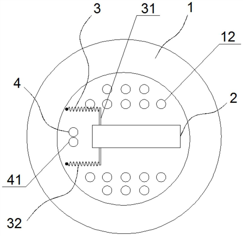
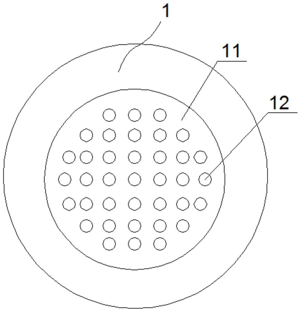
[0026] Such as Figure 1 to Figure 5 As shown, the present invention is a heating furnace with controllable combustion of charcoal, comprising: a shell 1 with a cover, the shell 1 is a hollow cavity, and a hole for connecting the inside and outside of the shell 1 is opened on the shell 1 The ventilation hole 12 is used to provide the carbon rod 5 with the oxygen required for combustion, and at the same time take out the heat of the carbon rod 5 after burning.

[0027] A carbon rod sleeve 2 for placing carbon rods 5 is fixed on the inner wall of the housing 1. The carbon rod sleeve 2 is rectangular as a whole, and it includes a carbon rod installation groove 21 and a carbon rod installation groove 21 that is detachably installed on the carbon rod sleeve 2. Loam cake 22, and one end of carbon rod installation groove 21 is charcoal outlet, on the upper wall and lower wall of carbon rod installation groove 21, all offer chute 23 along the length direction of carbon rod installatio...

Embodiment 2

[0031] The difference between Embodiment 2 and Embodiment 1 lies in the structure of the carbon rod sleeve 2 and the automatic reset device 32 .

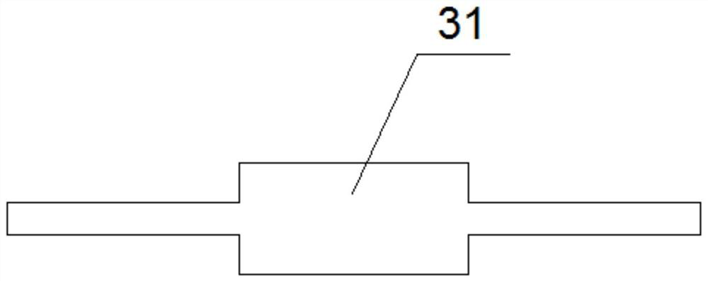
[0032] Such as Figure 6 As shown, the carbon rod sleeve 2 is arc-shaped, and the fixing bolt 41 is arranged at the carbon outlet of the carbon rod sleeve 2 . The automatic reset device 32 is a group, which is arranged on the inner side of the arc of the carbon rod sleeve 2. The spring 322 is a constant force spring. One end of the spring 322 is fixed on the housing 1 through a positioning piece 321, and the other end is connected to the pusher. The plate 31 is connected, and the carbon strip 5 drives the push plate 31 to slide in the carbon strip sleeve 2 through the spring 322 .

Embodiment 3

[0034] Embodiment 3 differs from Embodiment 1 and Embodiment 2 only in that the positions of the carbon rod sleeve 2 and the power mechanism 3 are different.

[0035] Such as Figure 7 As shown, the carbon rod sleeve 2 is rectangular, the power mechanism 3 is located in the carbon rod sleeve 2, the power mechanism 3 includes a push plate 31 and an automatic reset device 32, and the automatic reset device 32 includes a positioning member 321 and at least one set of springs 322, the positioning part 321 is arranged on the inner bottom of the carbon rod sleeve 2, and the spring 322 is an extension spring, and one end of the spring 322 is fixed on the carbon rod sleeve 2 through the positioning part 321, and the other end is connected with the push plate 31 connected, the carbon strip 5 drives the push plate 31 to slide in the carbon strip sleeve 2 through the spring 322 .

[0036] work process:

[0037] Before use, first ignite one end of the carbon rod 5, then put the carbon r...


PUM


Abstract

The invention belongs to the field of outdoor heating equipment, and provides a carbon combustion-controllable heating furnace which is provided for overcoming the defects that existing carbon blocks are short in combustion time and uneven in combustion temperature in the combustion heating process. The carbon combustion-controllable heating furnace comprises a shell with a cover, the shell is a hollow cavity, vent holes used for communicating the interior with the exterior of the shell are formed in the shell, a carbon strip sleeve used for containing a carbon strip is fixed to the inner wall of the shell, a carbon outlet is formed in one end of the carbon strip sleeve, a power mechanism and a blocking mechanism are further arranged on the inner wall of the shell, the power mechanism is used for pushing the carbon strip to move in the carbon strip sleeve, the blocking mechanism is fixed to the carbon outlet of the carbon strip sleeve, and the blocking mechanism is used for blocking the power mechanism from pushing the carbon strip out of the carbon strip sleeve. The carbon combustion-controllable heating furnace has the advantages of being simple and small in structure, convenient to carry, long in heating time and controllable in combustion speed.

Description

Technical field: [0001] The invention belongs to the technical field of outdoor heating equipment, in particular to a heating furnace with controllable charcoal combustion. Background technique: [0002] When carrying out outdoor activities for a long time in winter or in cold regions, in order to keep warm, people often choose electric heaters or hand stoves as heating equipment, and such products usually use electricity or charcoal as heating heat sources. Outdoor heating equipment needs to have the characteristics of small size, easy to carry, and long heating time. Although the electric heater is easy to carry, it is not suitable for the heating method of this product in the environment without power for a long time outdoors, so the charcoal hand stove is more suitable, but Since the charcoal block burns from the outer surface as a whole in the burning process, and then burns from the outside to the inside, the burning time will be short, the temperature fluctuates great...

Claims


Application Information

Patent Timeline
IPC IPC(8): F24B1/185F24B1/188F24B1/195
CPCF24B1/185F24B1/1885F24B1/195
Inventor 崔仁海徐振峰
Owner 哈尔滨雅德经贸有限公司
Learn More