dlp projection device

A projection device and lens technology, applied in projection devices, instruments, optics, etc., can solve the problems of high temperature of the projector, easy dust pollution, etc., reduce the difficulty of heat dissipation, avoid pollution or damage, improve projection effect and service life Effect

Active Publication Date: 2021-12-07
SHENZHEN YUANGUANGHAO ELECTRONICS
View PDF6 Cites 0 Cited by
  • Summary
  • Abstract
  • Description
  • Claims
  • Application Information

AI Technical Summary

Problems solved by technology

[0006] The purpose of the present invention is to provide a DLP projection device, the DLP projection device by arranging the light source and the optical path assembly in the heat dissipation cavity and the sealed cavity respectively, to solve the existing technology that the internal temperature of the projector is high and the dust easily pollutes the optical path assembly question

Method used


Image

  • dlp projection device
  • dlp projection device
  • dlp projection device

Examples


Embodiment approach

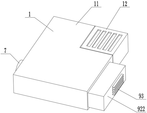
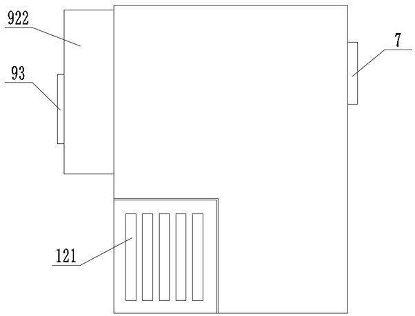
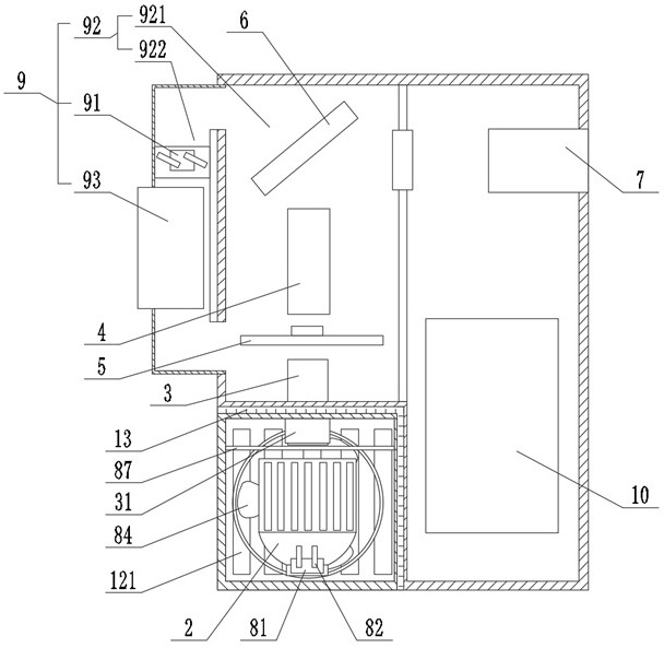
[0040] The second radiator 9 drives the air in the sealed chamber 11 to circulate, and dissipates the heat in the sealed chamber 11 through the fins 93 penetrating through the sealed chamber 11 . Such as image 3 As shown, according to an embodiment of the present invention, the second radiator 9 includes a circulation fan 91, a circulation flow channel 92 and a cooling fin 93, and the circulation flow channel 92 includes a first flow channel 921 and a second flow channel that communicate with each other. The flow channel 922, the first flow channel 921 is located in the sealed cavity 11, the optical path assembly is arranged in the first flow channel 921, the second flow channel 922 is located outside the sealed cavity 11, and the circulation The fan 91 is disposed in the second flow channel 922 , one end of the cooling fin 93 is disposed in the second flow channel 922 , and the other end is disposed outside the second flow channel 922 . By setting the circulation channel 92...


PUM


Abstract

The present invention relates to the field of projection devices, and discloses a DLP projection device, which includes a casing, a light source, a first lens, a second lens, a color wheel assembly and a digital micromirror element, and the casing includes an adjacent sealed cavity and a heat dissipation cavity, the light source is disposed in the heat dissipation cavity, the first lens is disposed on one side of the light source, the first lens penetrates the cavity wall between the sealed cavity and the heat dissipation cavity and is in contact with the heat dissipation cavity The sealed cavity is sealed and connected, the color wheel assembly, the second lens and the digital micromirror element are arranged in the sealed cavity, a first heat sink is arranged in the heat dissipation cavity, and the first heat dissipation The radiator is used to dissipate heat for the light source and the first lens, and a second radiator is arranged in the sealed cavity, and the second radiator is used to reduce the temperature of the sealed cavity. The DLP projection device respectively arranges the light source and the optical path assembly in the heat dissipation cavity and the sealed cavity, thereby preventing dust from entering the sealed cavity and polluting the optical path assembly.

Description

technical field [0001] The present invention relates to the field of projection devices, in particular to a DLP projection device. Background technique [0002] DLP is the abbreviation of "Digital Light Processing", that is, digital light processing, which means that this technology first processes the image signal digitally, and then projects the light. To be more specific, the DLP projection technology uses a digital micromirror chip as the main key processing element to realize the digital optical processing process. In a DLP projector, the image is generated by a DMD (Digital Micromirror Device, Digital Micromirror Device). DMD is a matrix composed of microlenses (precise, miniature mirrors) arranged on a semiconductor chip, and each microlens controls a pixel in the projection screen. [0003] Existing DLP projectors include a housing and a light source, a color wheel, a digital micromirror element and a lens arranged in the housing. The brightness of the projector ma...

Claims


Application Information

Patent Timeline
Patent Type & Authority Patents(China)
IPC IPC(8): G03B21/16G03B21/14
CPCG03B21/145G03B21/16
Inventor 李永晶白辉建
Owner SHENZHEN YUANGUANGHAO ELECTRONICS
Why Eureka
Try Eureka