Integral coil sleeving device and process for transformer machining

A technology of transformers and coils, which is applied to the field of coil integral set devices, can solve the problems of different diameters of transformer coils, inability to adjust the length of hooks, and inability to set transformer coils, etc.

Inactive Publication Date: 2021-04-09
ZHEJIANG POWER TRANSFORMER
View PDF6 Cites 2 Cited by
  • Summary
  • Abstract
  • Description
  • Claims
  • Application Information

AI Technical Summary

Problems solved by technology

[0003] In the prior art, in the processing of transformers, the transformer coils are directly mounted on the coils through the spreader. However, due to the different specifications of the transformers, the diameters of the transformer coils are different. When fitting the transformer coils, it is necessary to customize the exclusive spreader. It not only increases the processing cost of the transformer but also affects the processing efficiency. In addition, the length of the hook in most spreaders cannot be adjusted, so it cannot effectively fit transformer coils of different heights.

Method used


Image

  • Integral coil sleeving device and process for transformer machining
  • Integral coil sleeving device and process for transformer machining
  • Integral coil sleeving device and process for transformer machining

Examples


Embodiment 1

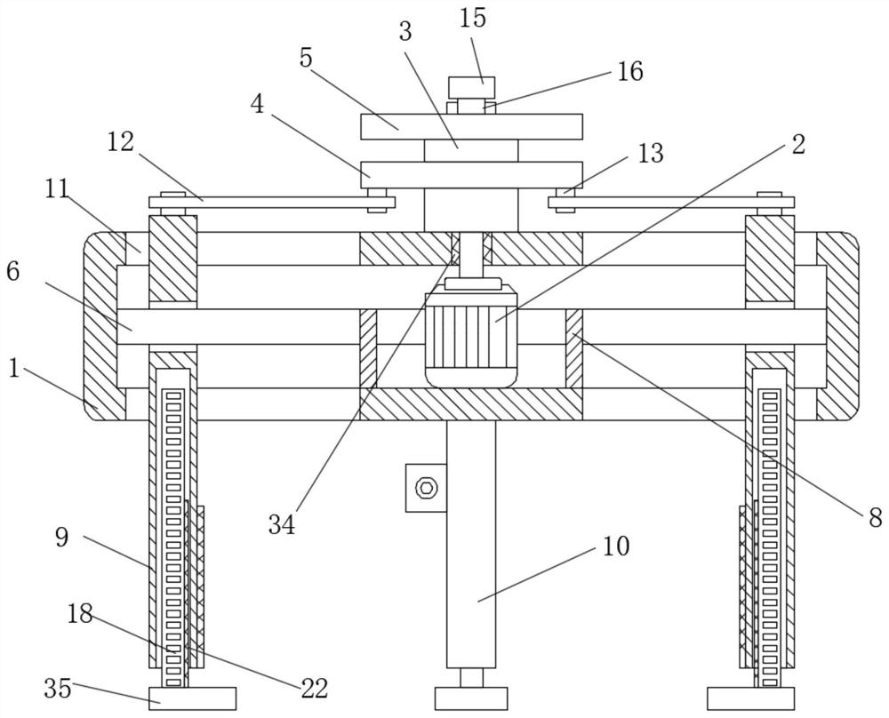
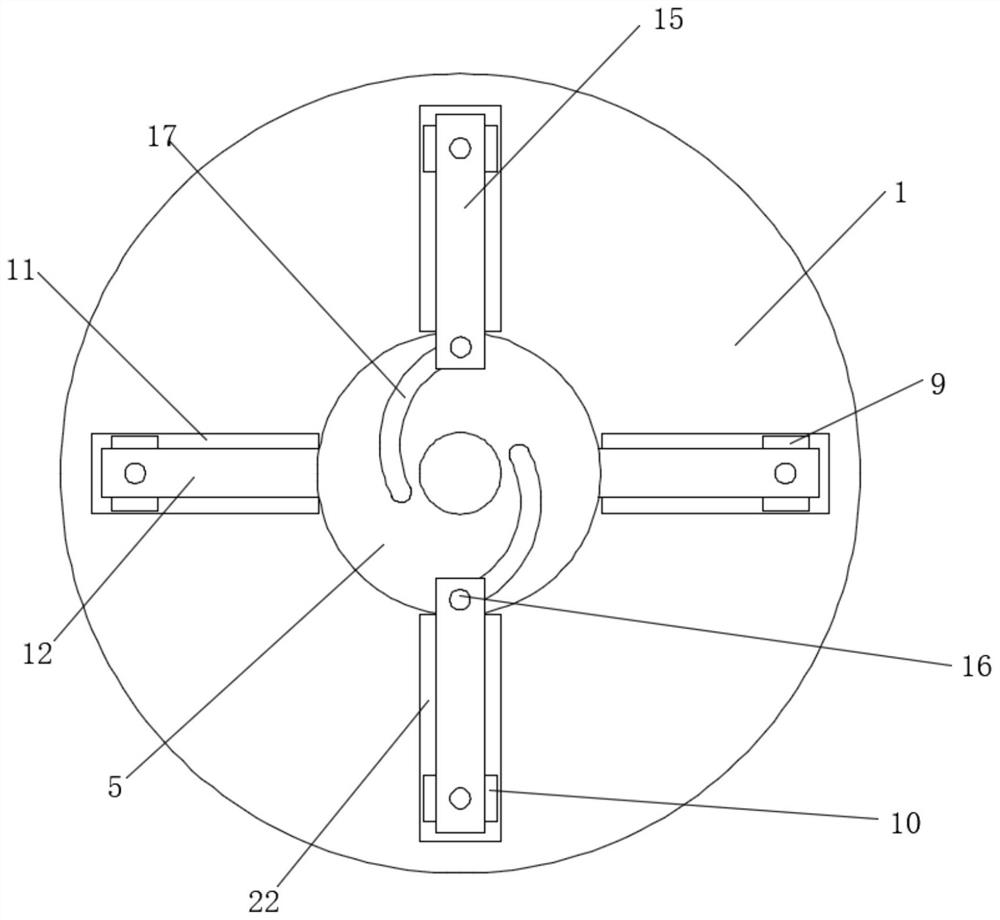
[0035] refer to Figure 1-7, a coil overall package device for transformer processing, including a casing 1, and the casing 1 is provided with two symmetrical first chute 11 and second chute 22, the inner walls on both sides of the two first chute 11 Both are slidably connected with a first sliding rod 9, and the inner walls of both sides of the two second chute 22 are slidably connected with a second sliding rod 10, and the housing 1 is provided with a function for making the two first sliding rods 9 and the two second The sliding rods 10 are driving components that move toward each other. The first racks 18 are slidably connected to the two first sliding rods 9, and the second racks 33 are slidably connected to the two second sliding rods 10. The bottom of the housing 1 There is a sliding assembly for controlling the sliding of the first rack 18 and the second rack 33 up and down, and the inner wall of the bottom of the housing 1 is fixedly connected with the cylinder 8 .

Embodiment 2

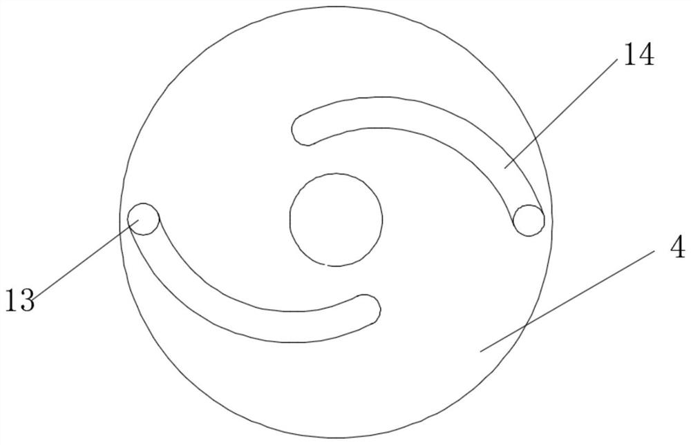
[0037] This embodiment is improved on the basis of Embodiment 1: the drive assembly includes a drive motor 2 fixedly connected to the inner wall of the bottom of the housing 1, the top of the housing 1 is rotatably connected to a rotating shaft 3, and the output shaft of the driving motor 2 runs through the housing 1 and connects with the rotating shaft The bottom end of 3 is fixedly connected, the outer wall of rotating shaft 3 is fixedly covered with a first disc 4 and a second disc 5, and the side of the first disc 4 deviated from the center of the circle is provided with two symmetrical first arc grooves 14 , the tops of the two first sliding rods 9 are rotatably connected with the first rotating rod 12, and the ends of the two first rotating rods 12 close to each other are fixedly connected with the first sliding block 13, and the top ends of the two first sliding blocks 13 Both extend into the first circular arc groove 14 and are all slidably connected with the first circ...


PUM


Abstract

The invention belongs to the technical field of transformer processing, and particularly relates to an integral coil sleeving device for transformer machining. For solving the problems that transformer coils of different specifications cannot be sleeved, and the length of a lifting hook in a lifting appliance cannot be adjusted, the integral coil sleeving device comprises a shell, and the integral coil sleeving device is simple and convenient. A worm and a rotating shaft can be driven to rotate by starting a rotating motor, the diameter of the device is controlled while the worm and the rotating shaft rotate, transformer coils of different heights can be clamped conveniently, a driving motor is started to drive a first disc and a second disc to rotate, and through rotation of the first disc and the second disc, the diameter of the device is conveniently regulated and controlled, then transformer coils with fixed diameters can be sleeved, the operation is convenient, the diameters and heights of the transformer coils with different specifications are adjusted, a special lifting appliance does not need to be customized, and the production cost is reduced.

Description

technical field [0001] The invention relates to the technical field of transformer processing, in particular to a coil overall package device and process for transformer processing. Background technique [0002] Transformer is a device that uses the principle of electromagnetic induction to change AC voltage. The main components are primary coil, secondary coil and iron core (magnetic core). The main functions are: voltage transformation, current transformation, impedance transformation, isolation, voltage stabilization (magnetic saturation transformer), etc. According to the use, it can be divided into: power transformers and special transformers (electric furnace transformers, rectifier transformers, power frequency test transformers, voltage regulators, mining transformers, audio transformers, intermediate frequency transformers, high frequency transformers, impact transformers, instrument transformers, electronic transformers , reactors, transformers, etc.). Circuit sy...

Claims


Application Information

Patent Timeline
Patent Type & Authority Applications(China)
IPC IPC(8): H01F41/00
CPCH01F41/00
Inventor 李崇墨夏敬军肖虎陈闯沈文俊叶全梯娄炤烜唐文才
Owner ZHEJIANG POWER TRANSFORMER
Why Eureka
Try Eureka