Rock-soil layer anti-backward anchor rod for mining

It is a technology of anti-regression and rock-soil layer, which is applied in mining equipment, bolt installation, earthwork drilling and mining, etc. It can solve problems such as easy loosening of the anchor head, falling off of the cement cohesive layer, retreating into the rock layer, etc., so as to prevent the anchor The effect of falling back

Active Publication Date: 2021-04-13
阳泉市广凯机械制造有限公司
View PDF4 Cites 0 Cited by
  • Summary
  • Abstract
  • Description
  • Claims
  • Application Information

AI Technical Summary

Problems solved by technology

[0005] The technical problem to be solved by the present invention is to provide a rock-soil anti-regression bolt for mining, one of the purposes of which is to have the anchor head and the rock layer firmly bonded together, so as to solve the problem that the anchor head is easy to loosen in the rock layer. Another purpose is to solve the problem that the entire anchor, including the cement bonding layer around the anchor, falls off together and falls back into the rock layer, so as to prevent the anchor from falling off through the hook tube and the hollow tip. retrograde effect

Method used


Image

  • Rock-soil layer anti-backward anchor rod for mining
  • Rock-soil layer anti-backward anchor rod for mining
  • Rock-soil layer anti-backward anchor rod for mining

Examples


Embodiment 1

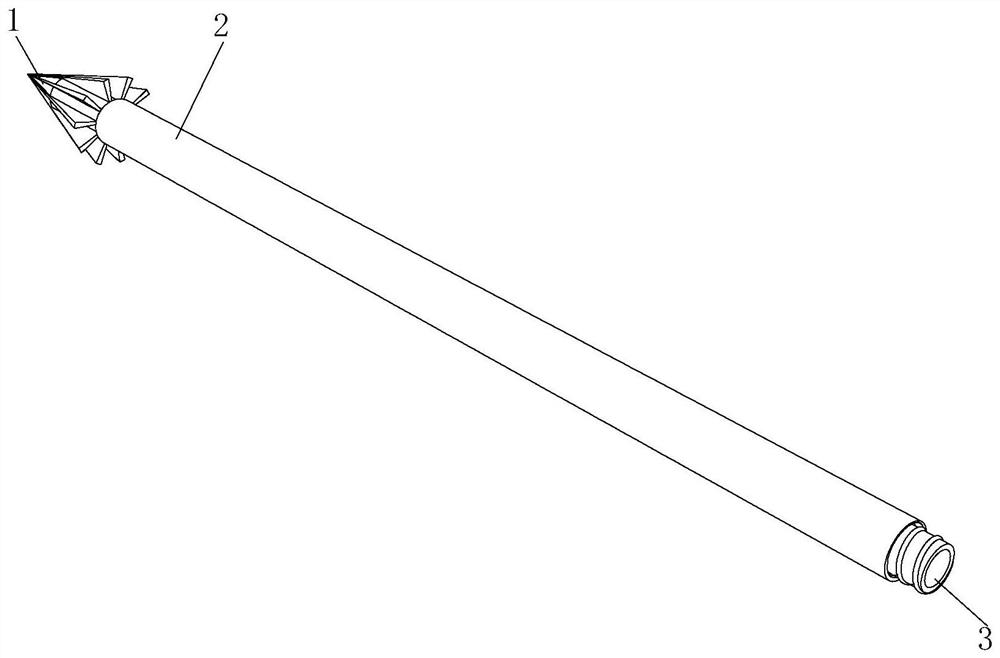
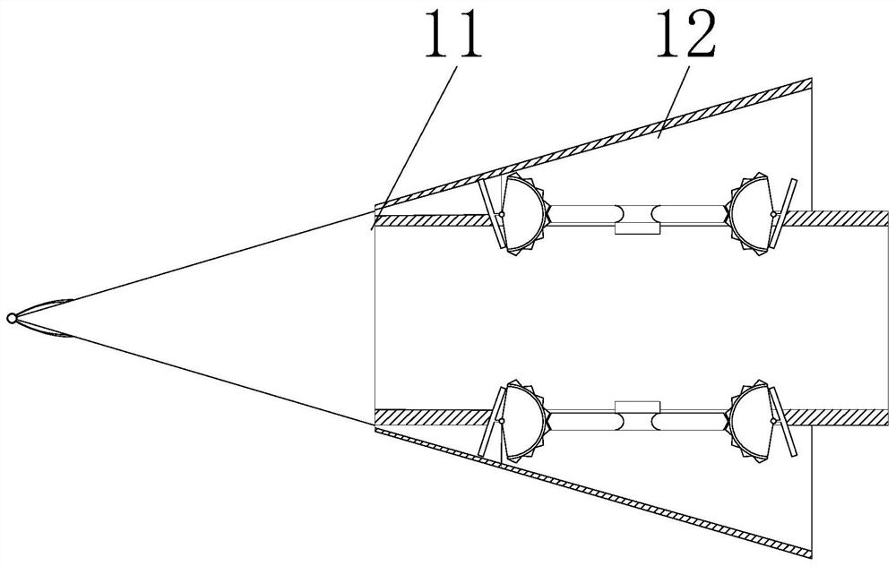
[0026] Such as Figure 1-Figure 6 As shown, the present invention provides a rock-soil layer anti-regression bolt for mining, comprising an anchor head 1, a rod body 2 and a bolt joint 3, the bottom of the anchor head 1 is movably connected with the top of the rod body 2, and the bottom of the rod body 2 is connected to the The top of the anchor joint 3 is threaded, the anchor head 1 includes a front drill bit 11 and a connection head 12, the bottom of the front drill bit 11 is fixedly connected with the top of the connection head 12, the front drill bit 11 includes a drill shell 111 and a cover plate 112, and the connection head 12 It includes a drill plate 121 , a hollow pipe 122 , a push block 123 , a hose 124 and a rotating gear 125 .

[0027] In this embodiment, a hollow anchor head 1 is used, and the anchor head 1 is divided into a front drill bit 11 and a connecting head 12, so that when the anchor rod is drilled into the rock and soil layer, it is convenient to inject ...

Embodiment 2

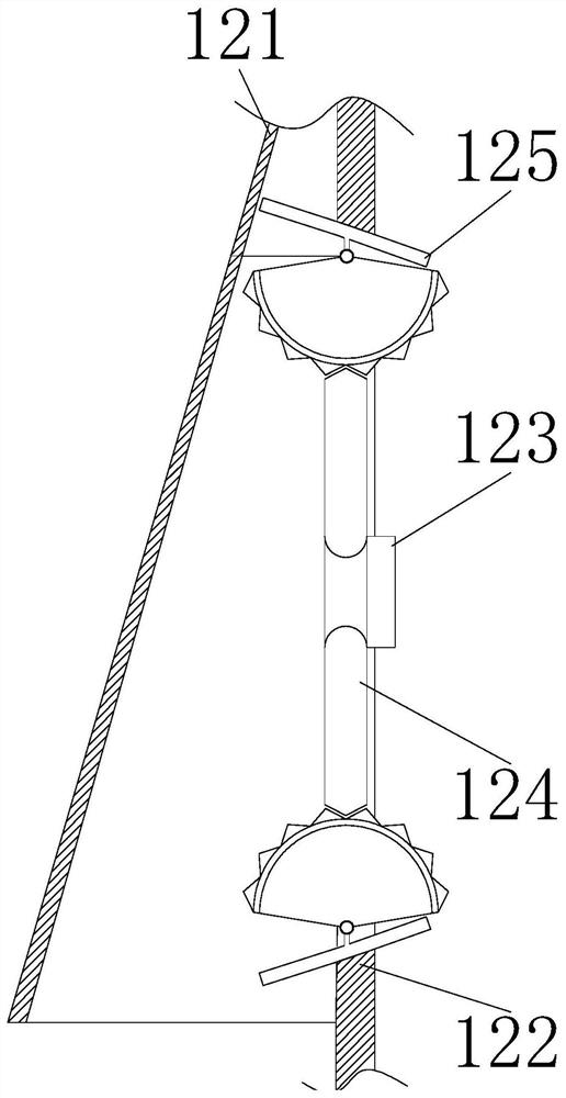
[0031] Such as Figure 3-4 As shown, on the basis of Embodiment 1, the present invention provides a technical solution: the bottom of the rotating gear 125 is fixedly connected to the top of the hose 124, the right end of the hose 124 is fixedly connected to the left side of the push block 123, and the soft The tube 124 includes a hose shell b1, a hollow tube b2 and a hollow tip b3, and the right side of the hose shell b1 is provided with a through hole, and the two ends of the inner wall of the hose shell b1 are provided with a card slot, and the inner wall of the card slot and the One end of the hollow tube b2 is clamped, and the outer wall of the hollow tube b2 is uniformly provided with several hollow pointed ends b3.

[0032] In this embodiment, the material of the hose 124 is a soft material, and the right side of the hose 124 is fixedly connected with a push block 123, wherein when cement is injected into the anchor rod, the cement is squeezed and pushed inside the holl...

Embodiment 3

[0034] Such as Figure 3-6 As shown, on the basis of Embodiment 1 and Embodiment 2, the present invention provides a technical solution: preferably, the cover plate 112 includes a rotating part d1 and a baffle plate d2, and slideways c6 are provided on both sides of the inner wall of the drill housing 111 , and both sides of the inner wall of the drill shell 111 are provided with arc-shaped grooves, and the arc-shaped grooves are located at the bottom of the slideway c6, the inner wall of the drill shell 111 is fixedly connected with a support spring c1, and the top of the support spring c1 is fixedly connected with a rotating ball c2, The bottom of the rotating ball c2 is rotatably connected with the inner wall of the drill housing 111, the top of the rotating ball c2 is fixedly connected with a compression spring c4, the inner wall of the slideway c6 is slidably connected with a hook tube c5, and the bottom of the hook tube c5 is fixedly connected with a pressure plate c3.

[...


PUM


Abstract

The invention discloses a rock-soil layer anti-backward anchor rod for mining, and relates to the technical field of mining engineering. The rock-soil layer anti-backward anchor rod comprises an anchor head, a rod body and an anchor rod joint, wherein drilling plates are uniformly arranged on the outer wall of a hollow tube; the inner wall of the hollow tube is movably connected with a rotary tooth part; the bottom of a rotary shaft is rotatably connected with the top of an arc-shaped tooth block; and a plurality of hollow sharp heads are uniformly arranged on the outer wall of the hollow tube. According to the rock-soil layer anti-backward anchor rod disclosed by the invention, the hollow sharp heads and the hollow tube are arranged, so that when cement is injected into the anchor rod, a pushing block extrudes a hose, and the hollow tube is ejected out by pressure, on the pushing block, of cement; the hollow sharp heads are arranged on the outer wall of the hollow tube, are tapered, and are inserted into a rock-soil layer, and cement flows into the hollow sharp heads along the hollow tube, so that the anchor rod and the rock-soil layer are bonded and fixed better; when cement flows into a front drill bit, a pressure plate is extruded, and a hook cover moves upwards along a slide path to eject out a drill shell; and a hook tube is in the shape of an inverted hook, so that the anchor rod is prevented from moving backwards to cause safety problems of mining workers or rock-soil collapse.

Description

technical field [0001] The invention relates to a bolt, which relates to the technical field of mining engineering, in particular to a rock-soil layer anti-regression bolt for mining. Background technique [0002] The bolt is the most basic part of roadway support in contemporary coal mines. It reinforces the surrounding rock of the roadway so that the surrounding rock can support itself. Anchor rods are not only used in mines, but also in engineering technology to carry out main body reinforcement for slopes, tunnels, and dam bodies. Anchor rods are rod system structures for rock and soil reinforcement. The tensile capacity of soil is far lower than the disadvantage of compressive capacity. On the surface, it restricts the separation of the rock and soil from the original body, and on the macroscopic view, it increases the cohesion of the rock and soil. There are following problems at prior art: [0003] 1. In the prior art, the bolts used in the mining process still hav...

Claims


Application Information

Patent Timeline
Patent Type & Authority Applications(China)
IPC IPC(8): E21D21/00E21D20/00E21D20/02
CPCE21D21/0026E21D21/008E21D20/003E21D20/028
Inventor 韩楠
Owner 阳泉市广凯机械制造有限公司
Why Eureka
Try Eureka