Supercharge Your Innovation With Domain-Expert AI Agents!

Wind driven generator

A technology for wind turbines and air inlet pipes, which is applied in the directions of wind turbines, wind turbine combinations, and wind power generation, can solve problems such as inability to protect, low power generation efficiency, detection, etc., so as to improve power generation efficiency and quality, and facilitate installation and disassembly. , the effect of improving power generation efficiency

Inactive Publication Date: 2021-04-13
曹青姣
View PDF9 Cites 2 Cited by
  • Summary
  • Abstract
  • Description
  • Claims
  • Application Information

AI Technical Summary

Problems solved by technology

[0004] The purpose of the present invention is to provide a wind power generator. By setting universal wheels, the problem that the traditional wind power generator is difficult to move is solved; by setting the wind direction detection board, it solves the problem that the traditional wind power generator cannot detect the wind direction, which leads to power generation efficiency. Low problem; by setting the extrusion block and the extrusion ring to squeeze and fit, the fan shaft is decelerated, which solves the problem that the existing wind turbine cannot be protected when the speed is too fast

Method used


Image

  • Wind driven generator
  • Wind driven generator
  • Wind driven generator

Examples


Embodiment 1

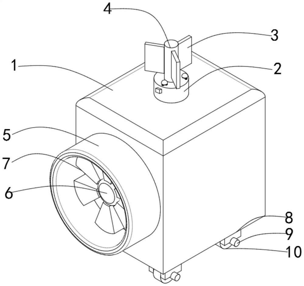
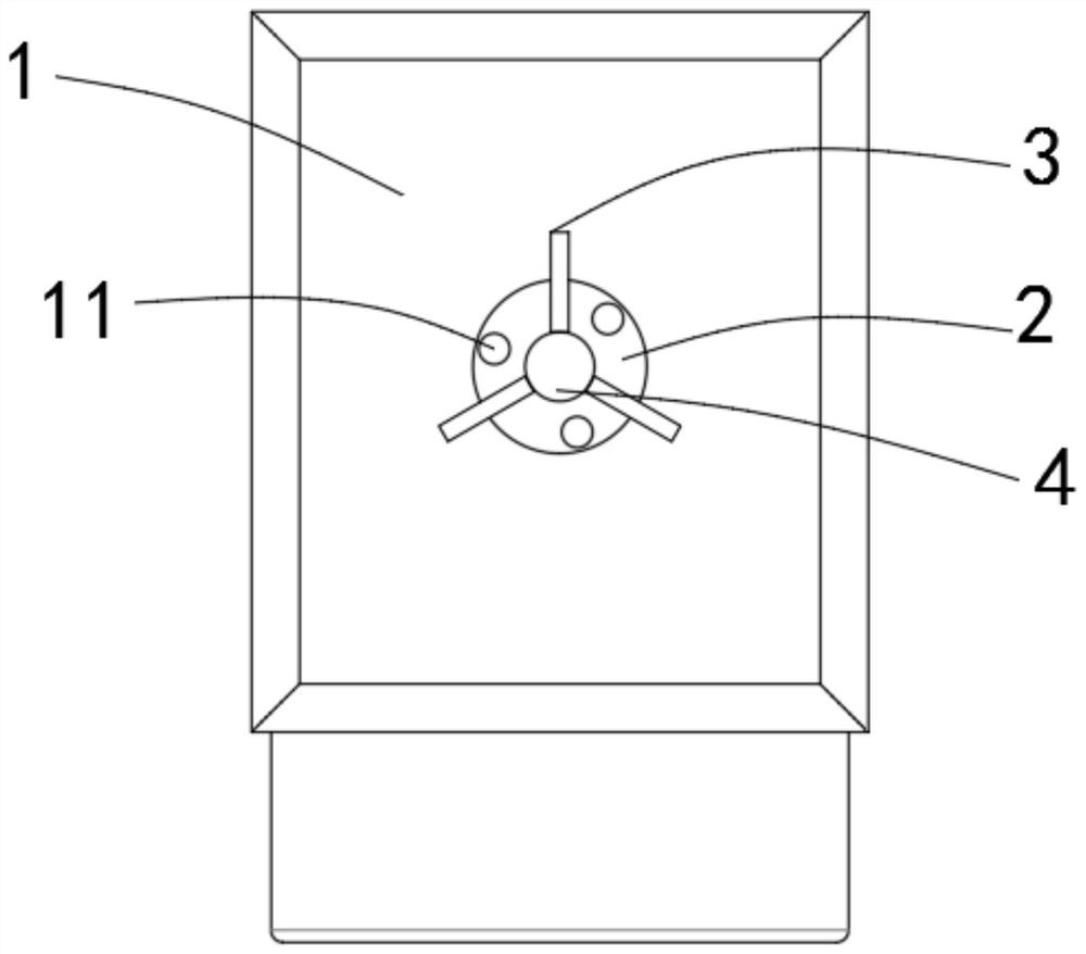
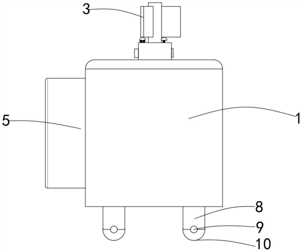
[0033] The following is a specific method of using a wind-driven generator: when using the present invention, first move the wind-powered generating box 1 to a corresponding position, detect the wind direction through the wind direction detection board 3, and then direct the air inlet duct 5 to the corresponding position, and then fix its position through the brake block 9, when the wind is too strong, the hydraulic device 16 will stretch the moving rod 17, so that the mounting plate 21 will slide, so that the second mounting block 23 will squeeze the first mounting block 15, making the extruding block 14 move, extruding the extruding ring 26, through the friction force between the two to make the fan rotating shaft 6 decelerate and rotate, and play a protective effect;

Embodiment 2

[0035] It should be further explained that when the wind force detection is completed, the wind force detection board 3 needs to be disassembled, and the first clamping block 29 is squeezed downward by pressing the pressing plate 11, and the second clamping block 31 is completely squeezed to the limit. In the position slot 36, the installation slider 33 can be pulled out of the first installation slot 27 by pressing the pressing plate 34 again.


PUM


Abstract

The invention discloses a wind driven generator, and relates to the technical field of wind power generation. The wind driven generator comprises a wind power generation box; the bottom surface of the wind power generation box is provided with mounting bases; the bottom surface of each mounting base is provided with a universal wheel; ring grooves, a bearing, a gear acceleration box, a generator and an extrusion ring are arranged in the wind power generation box; a sliding plate is mounted in each ring groove; one end of each sliding plate is connected with an extrusion block; the other side face of each extrusion block is fixedly provided with a first mounting block; one side face of a mounting support is provided with sliding rods and mounting plates, a connecting block is installed on one side face of each mounting plate; each connecting block is connected with a second mounting block; a mounting disc is installed on the upper surface of the wind power generation box; a rotating rod is arranged on the upper surface of the mounting disc; and wind direction detection plates are arranged on the circumferential side face of the rotating rod. According to the wind driven generator, by installing the universal wheels, the wind driven generator is convenient to move; the extrusion blocks are installed to be in extrusion fit with the extrusion ring, so that the situation that the equipment is damaged by the fact that the rotating speed of a rotating shaft is too high is prevented; and by installing the wind direction detection plates, wind direction detection is facilitated.

Description

technical field [0001] The invention belongs to the field of wind power generation, in particular to a wind power generator. Background technique [0002] Wind power refers to converting the kinetic energy of wind into electrical energy. Wind energy is a clean and pollution-free renewable energy source. It has been used by people for a long time, mainly through windmills to pump water and grind flour. People are interested in how to use wind to generate electricity. The use of wind power to generate electricity is very environmentally friendly and has a huge wind energy reserve, so it is increasingly valued by countries all over the world. Wind is one of the energy sources without pollution. And it is inexhaustible and inexhaustible. For coastal islands, grasslands, pastoral areas, mountainous and plateau areas that lack water, fuel, and inconvenient transportation, the use of wind power generation according to local conditions is very suitable and promising. Offshore wi...

Claims


Application Information

Patent Timeline
IPC IPC(8): F03D9/25F03D1/00F03D15/00F03D13/20F03D9/32F03D7/04G01P13/02G01P1/00
CPCF03D1/00F03D7/0248F03D7/0268F03D9/25F03D9/32F03D13/20F03D15/00G01P1/00G01P13/02Y02E10/72Y02E10/728
Inventor 曹青姣
Owner 曹青姣
Features
  • R&D
  • Intellectual Property
  • Life Sciences
  • Materials
  • Tech Scout
  • Unparalleled Data Quality
  • Higher Quality Content
  • 60% Fewer Hallucinations
Learn More