Ultrahigh-pressure exhaust valve

A technology of ultra-high pressure and exhaust valves, applied in valve details, valve devices, valve operation/release devices, etc., can solve problems such as seal failure, seal damage, and difficulty in opening again, so as to ensure seal reliability and prevent Excessive compression, which facilitates the effect of opening the seal

Pending Publication Date: 2021-04-13
SHANGHAI KARON VALVES MACHINERY
6 Cites 2 Cited by

AI-Extracted Technical Summary

Problems solved by technology

[0004] 1. When the buoyancy is guaranteed, the volume of the traditional stainless steel floating ball increases, and the rigidity of the external pressure is not enough, which is easy to cause instability and damage; if the rigidity is ensured, the wall thickness becomes thicker and the weight increases; this creates a contradiction that is not conducive to the design. more difficu...

Method used

[0039] The present invention can truly realize the exhaust function under ultra-high pressure. The floating ball is made of polymer material, which ensures the strength of the floating ball, and at the same time, the volume will not be too large when the buoyancy is satisfied; the sealing surface is made of high hard rubber or polymer material polyurethane as the sealing ring, and the multi-layer stainless steel and graphite pla...

Abstract

The invention relates to an ultrahigh-pressure exhaust valve comprising a main valve and a trace exhaust valve group. The lower end of the main valve communicates with a pipeline, the main valve is used for achieving large-amount low-pressure exhaust and large-amount air suction, and the main valve comprises a main valve body, a main valve deck installed on the top of the main valve body and provided with a first exhaust hole, a main valve floating ball assembly installed in the main valve body and a throttling exhaust assembly installed on the upper portion of the main valve deck. The trace exhaust valve group is connected with the main valve and is used for achieving high-pressure automatic exhaust. The trace exhaust valve group comprises a trace exhaust valve group valve body, a trace exhaust valve group valve deck, a sealing base and a floating ball lever assembly. The bottom of the trace exhaust valve group valve body communicates with the lower part of the main valve body, and the upper part of the trace exhaust valve group valve body is fixedly connected with the main valve body. The trace exhaust valve group valve deck is arranged on the top of the trace exhaust valve group valve body. The sealing base is arranged on the trace exhaust valve group valve deck and is used for achieving trace exhaust. The floating ball lever assembly is fixed to the trace exhaust valve group valve deck and is used for achieving opening and closing of the sealing base. Compared with the prior art, the ultrahigh-pressure exhaust valve has the advantages of being high in strength, good in sealing performance, capable of preventing overcompression and capable of achieving rapid and stable opening through the eccentric fit lever principle.

Application Domain

Technology Topic

Image

  • Ultrahigh-pressure exhaust valve
  • Ultrahigh-pressure exhaust valve

Examples

  • Experimental program(1)

Example Embodiment

[0034] Example
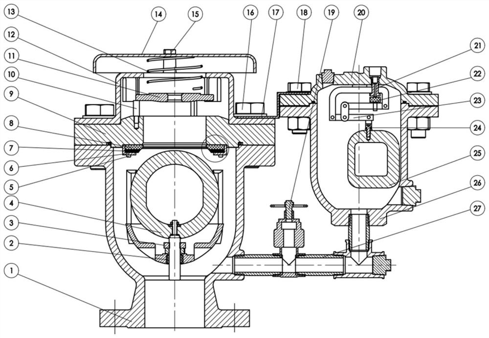
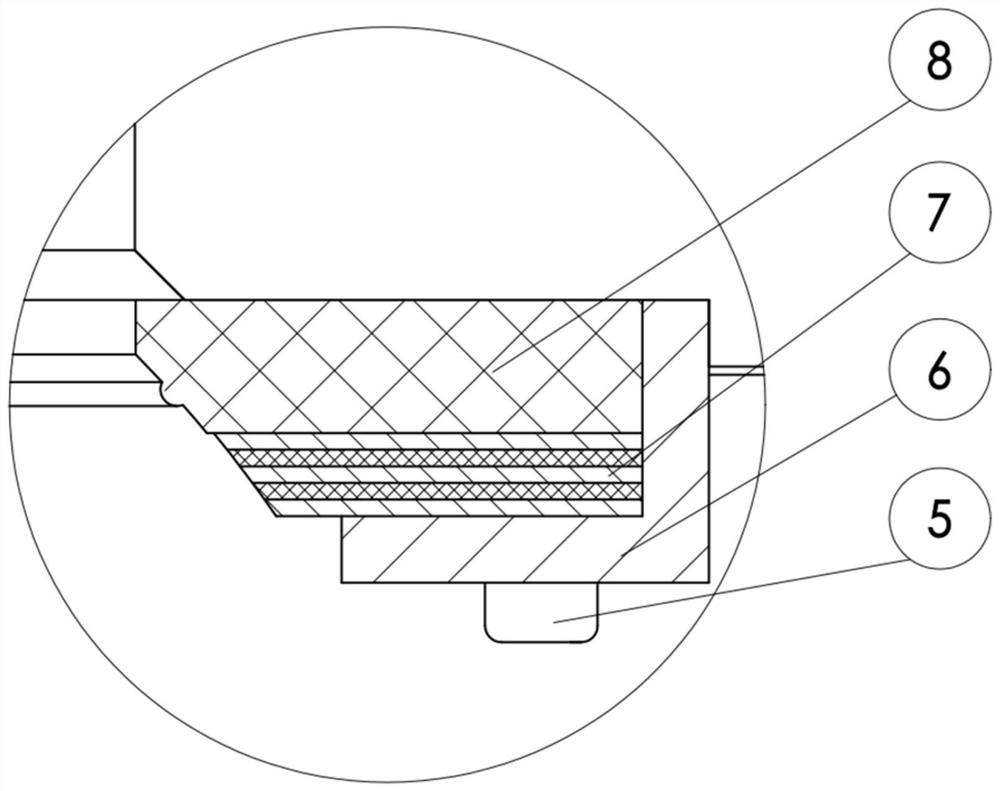
[0035] like figure 1 and 2 As shown, the present invention provides an ultra-high pressure exhaust valve, which is suitable for ultra-high pressure environments with a pressure rating of PN63 and above. The exhaust valve is mainly composed of a main valve and a trace exhaust valve group. , the main valve is used to realize a large amount of low-pressure exhaust and a large amount of air intake, and the micro-exhaust valve group is used to realize high-pressure automatic exhaust. The main valve float assembly 4, seal frame 6, limit plate 7, seal ring 8, throttle ring 11, buffer frame 12, spring 13, exhaust cover 14 and other parts are composed of the main valve float assembly; the micro exhaust valve group is mainly composed of Valve body, micro-exhaust valve group bonnet 20, top plug 22, sealing seat 21, lever assembly 22 (lever, lever frame, hinge, pin), micro-exhaust valve group made of hollowed out polymer material Float 25, float fork and other parts are formed.
[0036] The main valve body 1 is connected and fastened with the main valve bonnet 9 and the buffer frame 12 through bolts and gaskets 16, the guide sleeve 2 is fixed in the inner cavity of the main valve body 1 through threads, and the main valve float assembly 4 passes through the guide The sleeve 2 and the buffer pad 3 can freely float up and down in the main valve body 1. The sealing frame 6 presses the limit plate 7 and the sealing ring 8 tightly on the main valve bonnet 9 in turn, and is fixed by the screw 5 to throttle the flow. The ring 11 is horizontally placed on a plurality of positioning studs 10, and moves up and down under the limit of the ribs inside the buffer frame 12. The spring 13 is placed between the throttle ring 11 and the exhaust cover 14 to provide the throttle ring 11. Close the damping and reset the required force value, the exhaust cover 14 is fixed on the buffer frame 12 through the bolt 15, the main valve body 1 and the micro exhaust valve group valve body 26 are connected together through the joint 27 and the gate valve 19, the fixed plate 17 The main valve and the micro exhaust valve group are connected and fixed by bolts and gaskets 16, bolts, nuts and gaskets 18, and the micro exhaust valve group valve body 26 and the micro exhaust valve group valve cover 20 are connected through bolts, nuts and gaskets. The sheet 18 is fixed, the lever assembly 23 is fixed on the valve cover 20 of the micro exhaust valve group, the sealing seat 21 is fixed on the valve cover 20 of the micro exhaust valve group, the top plug 22 is installed on the lever assembly 23, and the micro exhaust valve The group of floating balls 25 is fixed on the lever assembly 23 by screws 24 .
[0037]When water starts flowing in the pipeline, the exhaust valve starts to exhaust a large amount of air; when the pressure difference between the top and bottom of the throttle ring 11 reaches a certain value, the throttle ring 11 starts to leave the positioning stud 10, and the compression spring 13 moves upward until it is in contact with the main valve. When the valve cover 9 contacts, it begins to throttle and exhaust, so as to prevent the pressure in the valve from rising too fast. When the water level in the pipeline starts to rise, the main valve float assembly 4 is buoyantly raised until it contacts the seal ring 8 to form a seal; the water pressure continues to rise, the seal ring 8 is compressed to a certain extent, and the main valve float assembly 4 will be in contact with the limit Plate 7 contact prevents excessive compression of sealing ring 8 . At this time, even if the sealing ring 8 is damaged and fails, the limiting plate 7 can also play the role of sealing. The floating ball 25 of the micro exhaust valve group is subjected to buoyancy and continues to rise so that the top plug 22 contacts and seals with the sealing seat 21 . When the dissolved gas in the water continues to accumulate at a high level, the water level of the micro-exhaust valve group drops, and the floating ball 25 of the micro-exhaust valve group loses buoyancy and falls. Micro automatic exhaust. When the water level in the pipeline drops and negative pressure occurs, the main valve float assembly 4 falls, and the valve can be opened to absorb a large amount of air to eliminate the negative pressure.
[0038] When the pipeline starts to pass water, the main valve begins to exhaust a large amount of air, and the air pressure in the main valve rises sharply; The buoyancy is closed, which can effectively prevent the air pressure from being too large. The floating ball is temporarily closed by the air pressure, causing the floating ball to be damaged by excessive impact force. When the buoyancy is closed, the dissolved gas in the pipeline continues to accumulate at a high level, causing the liquid level of the micro-exhaust valve group to drop, and the float loses buoyancy; due to the center of gravity offset design of the float, the superimposed leverage amplifies the force, and the micro-exhaust The floating ball of the valve group will force the top plug to break away from the sealing surface, and it will not be sucked even if the pressure is high, so as to realize a small amount of automatic exhaust under ultra-high pressure. When the water level in the pipeline drops and negative pressure occurs, the main valve floating ball will Falling, the exhaust valve is opened again to realize a large amount of suction function and prevent the negative pressure from damaging the pipeline.
[0039] The invention can truly realize the exhaust function under ultra-high pressure. The floating ball is made of polymer material, which ensures the strength of the floating ball, and at the same time, the volume is not too large when the buoyancy is satisfied; the sealing surface is made of high hard rubber or polymer material polyurethane as the sealing ring, and the multi-layer stainless steel and graphite plate interlayer As a limit plate, this combined sealing structure increases the sealing reliability under high pressure; the micro exhaust valve group uses the leverage principle to amplify the gravity of the floating ball to ensure that the seal can be opened under ultra-high pressure; the micro exhaust valve group floats The eccentric weight of the ball can accelerate the drop of the floating ball and assist in opening the seal.

PUM

no PUM

Description & Claims & Application Information

We can also present the details of the Description, Claims and Application information to help users get a comprehensive understanding of the technical details of the patent, such as background art, summary of invention, brief description of drawings, description of embodiments, and other original content. On the other hand, users can also determine the specific scope of protection of the technology through the list of claims; as well as understand the changes in the life cycle of the technology with the presentation of the patent timeline. Login to view more.

Similar technology patents

Electrode module for flow battery, preparation method of electrode module and battery stack containing electrode module

InactiveCN105047945AReduce contact resistancePrevent overcompressionCell electrodesFuel cell detailsEngineeringIntegrated design
Owner:中国东方电气集团有限公司

bogie

ActiveCN110576879BImprove stabilityPrevent overcompressionBogiesBogie-underframe connectionsEngineeringBogie
Owner:DATONG ELECTRIC LOCOMOTIVE OF NCR

Rotary compressor

ActiveCN110520624APrevent overcompressionReduce indicator lossRotary piston pumpsRotary piston liquid enginesRefrigerantDrive motor
Owner:LG ELECTRONICS INC

Classification and recommendation of technical efficacy words

  • Prevent overcompression
  • Guaranteed sealing reliability

Inhaler Valve

InactiveUS20080011291A1Prevent overcompressionCrimp tightMedical atomisersLiquid dispensingBiomedical engineeringInhaler
Owner:FLETCHER IAN +2

Picture compression method and system based on mobile terminal

Owner:杭州吉吉知识产权运营有限公司

Rotary compressor

ActiveCN110520624APrevent overcompressionReduce indicator lossRotary piston pumpsRotary piston liquid enginesRefrigerantDrive motor
Owner:LG ELECTRONICS INC

Electrode module for flow battery, preparation method of electrode module and battery stack containing electrode module

InactiveCN105047945AReduce contact resistancePrevent overcompressionCell electrodesFuel cell detailsEngineeringIntegrated design
Owner:中国东方电气集团有限公司

Ball valve

ActiveCN103511657AGuaranteed sealing reliabilityPlug valvesPhysicsBall valve
Owner:NEWAY VALVE SUZHOU

Adjustable multifunctional combined joint structure

PendingCN112361102AGuaranteed locking torqueGuaranteed sealing reliabilityAdjustable jointsStructural engineeringClassical mechanics
Owner:GUANGXI YUCHAI MASCH CO LTD

Paper cup bowl and paper cup bowl curled edge molding mould

PendingCN108943858AImprove bearing strengthGuaranteed sealing reliabilityPaper-makingBox making operationsEdge structurePaper cup
Owner:ZHEJIANG NEW DEBAO MACHINERY
Why Eureka
Try Eureka