
Stator structure of vibration motor

A stator structure and vibrating motor technology, applied in the field of vibrating motors, can solve problems such as power line circuit short circuit, generate a lot of heat, and be difficult to dissipate, and achieve the effects of increasing contact area, improving heat dissipation performance, and improving service life

Inactive Publication Date: 2021-04-13
湖北恒高电子有限公司
View PDF8 Cites 0 Cited by
  • Summary
  • Abstract
  • Description
  • Claims
  • Application Information

AI Technical Summary

Problems solved by technology

[0003] There are still various problems in the use of existing vibration motors. When the rotor of the vibration motor rotates at high speed, the rotation of the coil will generate a lot of heat, which is difficult to dissipate, causing the coil to burn out, and the power line will cause a short circuit. cause fire and other dangers, for this reason we propose a stator structure for vibration motors

Method used


Image

  • Stator structure of vibration motor
  • Stator structure of vibration motor
  • Stator structure of vibration motor

Examples


Embodiment Construction

[0020] In order to make the technical means, creative features, goals and effects achieved by the present invention easy to understand, the present invention will be further elaborated below in conjunction with specific embodiments, but the following embodiments are only preferred embodiments of the present invention, not all. Based on the examples in the implementation manners, other examples obtained by those skilled in the art without making creative efforts all belong to the protection scope of the present invention. The experimental methods in the following examples, unless otherwise specified, are conventional methods, and the materials, reagents, etc. used in the following examples, unless otherwise specified, can be obtained from commercial sources.

[0021] Example:

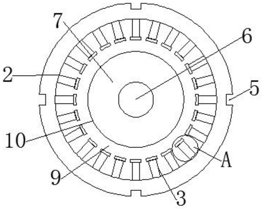
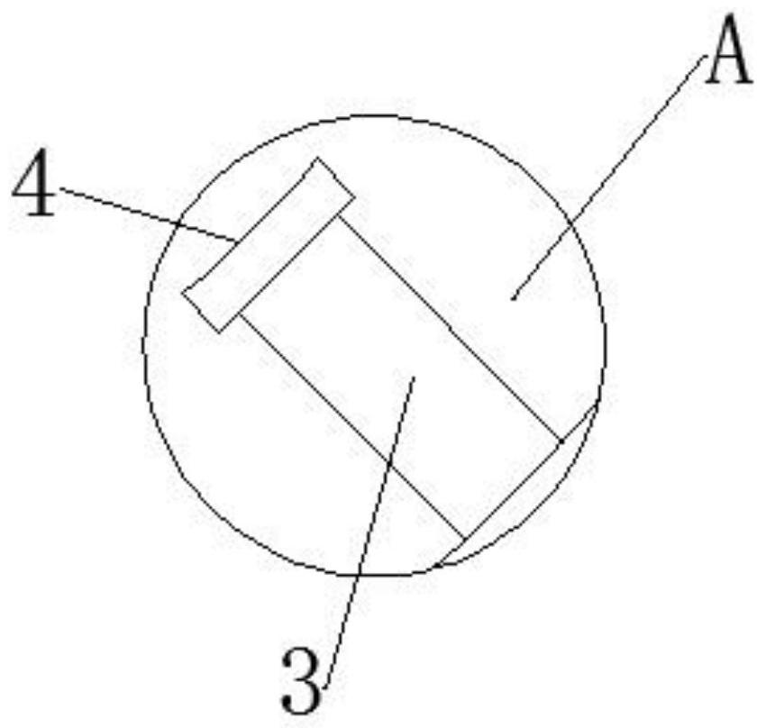
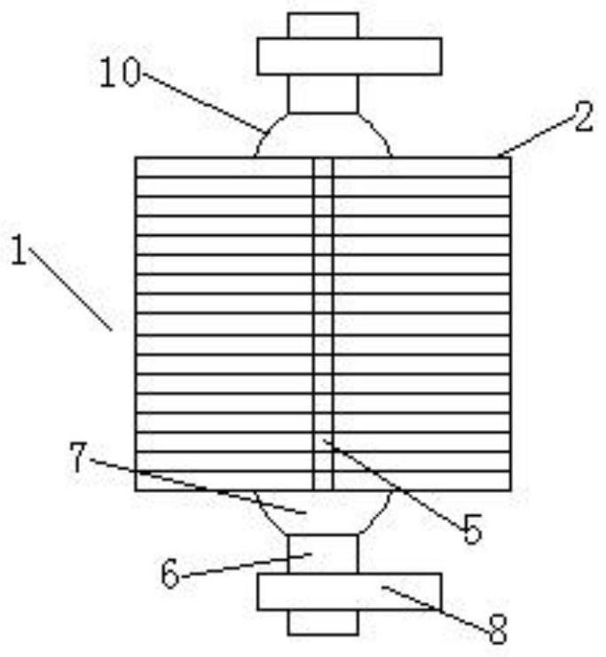
[0022] like figure 1 and image 3 As shown, the present invention provides a stator structure of a vibrating motor, including a motor casing, a rotating shaft 6, a rotating shaft 6 is fixedly installed...


PUM


Abstract

The invention discloses a stator structure of a vibration motor. The stator structure comprises a motor shell and a rotating shaft, wherein the rotating shaft is fixedly arranged in the motor shell, a rotor is coaxially and fixedly arranged on the rotating shaft, coils are fixedly arranged on the rotor, a stator is fixedly arranged in the motor shell, and is formed by stacking single stators, heat dissipation grooves are formed in the periphery of the single stator, a plurality of uniformly distributed winding posts are fixedly mounted in the single stator, the coils are fixedly mounted between the winding posts, and air channels are formed between the winding posts and the rotor. According to the invention, the operation of the motor is achieved through the stator and the rotor arranged in the motor shell; the stator is composed of a plurality of single stators, so that the heat dissipation performance of the stator is improved, and the contact area between the coil and the stator is increased; and the stator is cooled through the heat dissipation grooves formed in the single-piece stators, so that the coil is protected, the practicability of the device is improved, and the service life of the device is prolonged.

Description

technical field [0001] The invention relates to the field of vibration motors, in particular to a stator structure of a vibration motor. Background technique [0002] The vibration motor installs a set of adjustable eccentric blocks at both ends of the rotor shaft, and uses the centrifugal force generated by the high-speed rotation of the shaft and eccentric blocks to obtain the exciting force. The vibration frequency range of the vibration motor is large, and the mechanical noise can only be reduced if the excitation force and power are properly matched. Vibration motors are classified into six categories according to the starting and running mode and the operating speed. [0003] There are still various problems in the use of existing vibration motors. When the rotor of the vibration motor rotates at high speed, the rotation of the coil will generate a lot of heat, which is difficult to dissipate, causing the coil to burn out, and the power line will cause a short circuit...

Claims


Application Information

Patent Timeline
Patent Type & Authority Applications(China)
IPC IPC(8): H02K1/20H02K3/52H02K7/065H02K7/075
CPCH02K1/20H02K3/522H02K7/065H02K7/075
Inventor 刘弟军刘培刚
Owner 湖北恒高电子有限公司
Learn More