
Dryer cartridge, drying system, and use thereof

A drying system and dryer technology, applied in chemical instruments and methods, dispersed particle filtration, gas treatment, etc., to achieve full contact effect

Pending Publication Date: 2021-04-13
MANN HUMMEL GMBH
View PDF7 Cites 0 Cited by
  • Summary
  • Abstract
  • Description
  • Claims
  • Application Information

AI Technical Summary

Problems solved by technology

Therefore, this device is only suitable for absorbing free water that has collected at the bottom of the tank

Method used


Image

  • Dryer cartridge, drying system, and use thereof
  • Dryer cartridge, drying system, and use thereof
  • Dryer cartridge, drying system, and use thereof

Examples


Embodiment Construction

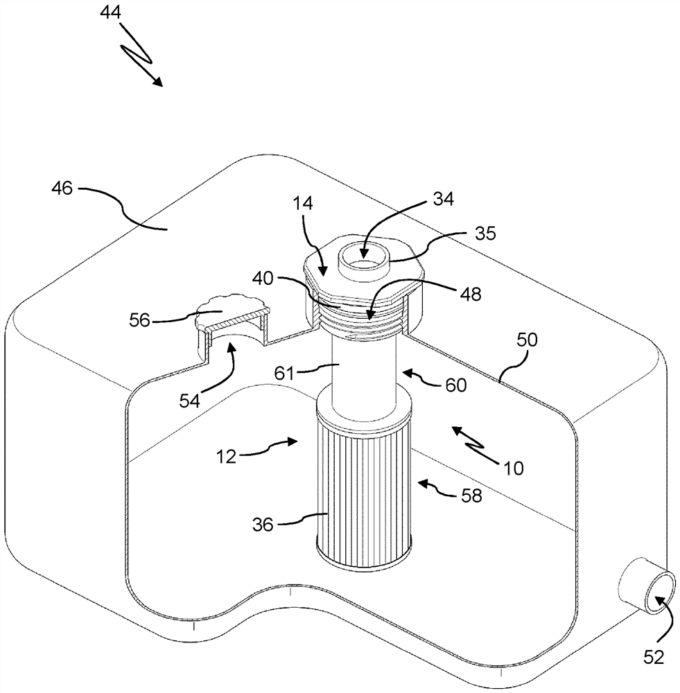
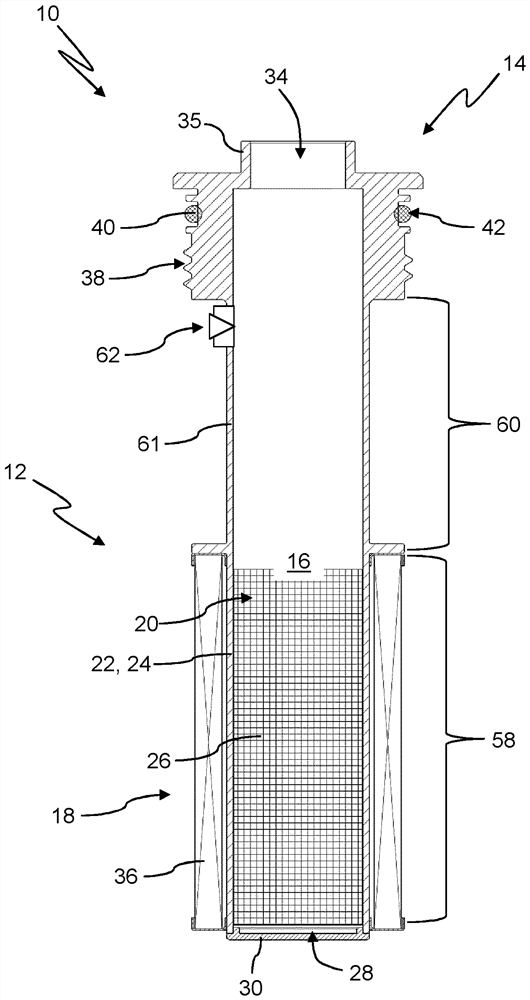
[0036] figure 1 The dryer core box 10 is shown in a schematic longitudinal section. The dryer core box 10 includes a core box body 12 and a connection head 14 .

[0037] The core box body 12 includes a receiving chamber 16 . The receiving chamber 16 is surrounded by a wall 18 through which liquid can flow. Here, the flow wall 18 is formed by a sieve 20 . The screen 20 may be implemented in one piece with the core box body 12 . Currently, the screen 20 is designed as a separate component from the core box body 12 and inserted into the core box body 12 . The screen 20 has a closed configuration in the circumferential direction and at the end faces at both sides. Here, the screen 20 is internally supported by the grid-type support structure 22 of the dryer core box 10 . exist figure 1 In the longitudinal struts 24 extending longitudinally of the grid-type support structure 22 can be seen; in the present view, the transverse struts extending in the circumferential direction...


PUM

PropertyMeasurementUnit
porosityaaaaaaaaaa
particle sizeaaaaaaaaaa

Abstract

The invention relates to a dryer cartridge (10) for removing water from a fluid, in particular oil, comprising a cartridge body (12) that forms a receiving chamber (16) in which a drying agent is received, said receiving chamber (16) being delimited at least partly by a wall (18) of the cartridge body (12), through which wall the fluid can flow, and comprising a connection head (14) for securing the dryer cartridge (10) in an opening (48) of a housing wall (50) of a device for receiving the fluid, preferably in a releasable manner, wherein the connection head (14) has a connection opening (34) which fluidically connects the receiving chamber (16) to a surrounding area. According to the invention, when the dryer cartridge (10) is used to dry a fluid, the fluid flows through the connection opening (34).

Description

technical field [0001] The present invention relates to a dryer core box for removing water from a fluid, in particular oil, said dryer core box having a core box body forming a receiving chamber in which a desiccant is received, wherein , the receiving chamber is delimited, at least in its section, by a wall of the core box body, through which wall a fluid can flow. Furthermore, the invention relates to a drying system with such a dryer core box and the use thereof. Background technique [0002] In fluid transfer systems, due to various processes it can happen that water collects in the fluid. Water can reach the system, eg by air exchange with the environment, and collect in the fluid. Likewise, free water can be introduced into the system from the environment. Water can be present in the fluid as free water or dissolved water. Water in the fluid can lead to desirable pulmonary effects such as, for example, corrosion of the fluid transport components of the system, an ...

Claims


Application Information

Patent Timeline
Patent Type & Authority Applications(China)
IPC IPC(8): B01D17/02B01D53/04B01D53/26B01D46/00
CPCB01D17/0202B01D53/0415B01D53/261B01D46/0036B01D2253/108B01J20/18B01J2220/62B01J20/2805B01J20/28052B01J20/28085B01J20/10B01J20/041B01J20/045B01J20/043B01J20/08B01J20/103B01J2220/49B01J20/28045B01J20/28083B01D2257/80F02M25/0854F02M2025/0863F02M37/24
Inventor A·特劳特M·潘策尔
Owner MANN HUMMEL GMBH
Learn More