Heating device of washing and dyeing device

A heating device and equipment technology, applied in the direction of processing textile materials equipment configuration, etc., can solve the problems of affecting the quality of washing and dyeing, increasing the water ratio, and increasing the inner space of the outer barrel, so as to ensure the quality of washing and dyeing, save the proportion of use, reduce the The Effect of Laundry and Dyeing Costs

Active Publication Date: 2015-11-04
广州市番禺区沙湾同心机器厂
View PDF4 Cites 0 Cited by
  • Summary
  • Abstract
  • Description
  • Claims
  • Application Information

AI Technical Summary

Problems solved by technology

[0004] Although this heating device can basically realize the heating work of the washing liquid and / or dyeing liquid, it still has deficiencies, for example: 1. The heating elbow is arranged on the inner bottom of the outer barrel, which will occupy the inner space of the outer barrel. In the case of a large amount of washing and dyeing, it is necessary to increase the inner space of the outer barrel, and the corresponding amount of washing liquid and / or dyeing liquid will increase accordingly. While increasing the water ratio, it will cause waste of dyes, thereby increasing the cost of washing and dyeing
2. The heating elbow is soaked in the washing solution and / or dyeing solution in the outer barrel, which is easy to be corroded and has a low service life
3. If the heating elbow is placed in the outer barrel, during dyeing and washing, the wool and thread ends falling off the fabric will gather or hang on the heating elbow, and the dye solution remaining on it is difficult to clean , which will ultimately affect the quality of subsequent washing and dyeing (for example, when changing dye solutions of different colors, the residual dye solution will mix with the replaced dye solution, resulting in a change in the color of the replaced dye solution, which will eventually affect the quality of washing and dyeing); 4 , The side wall of the outer barrel is made of thin metal plate, the heat dissipation speed is fast, and the heat loss is relatively serious

Method used


Image

  • Heating device of washing and dyeing device
  • Heating device of washing and dyeing device
  • Heating device of washing and dyeing device

Examples


Embodiment Construction

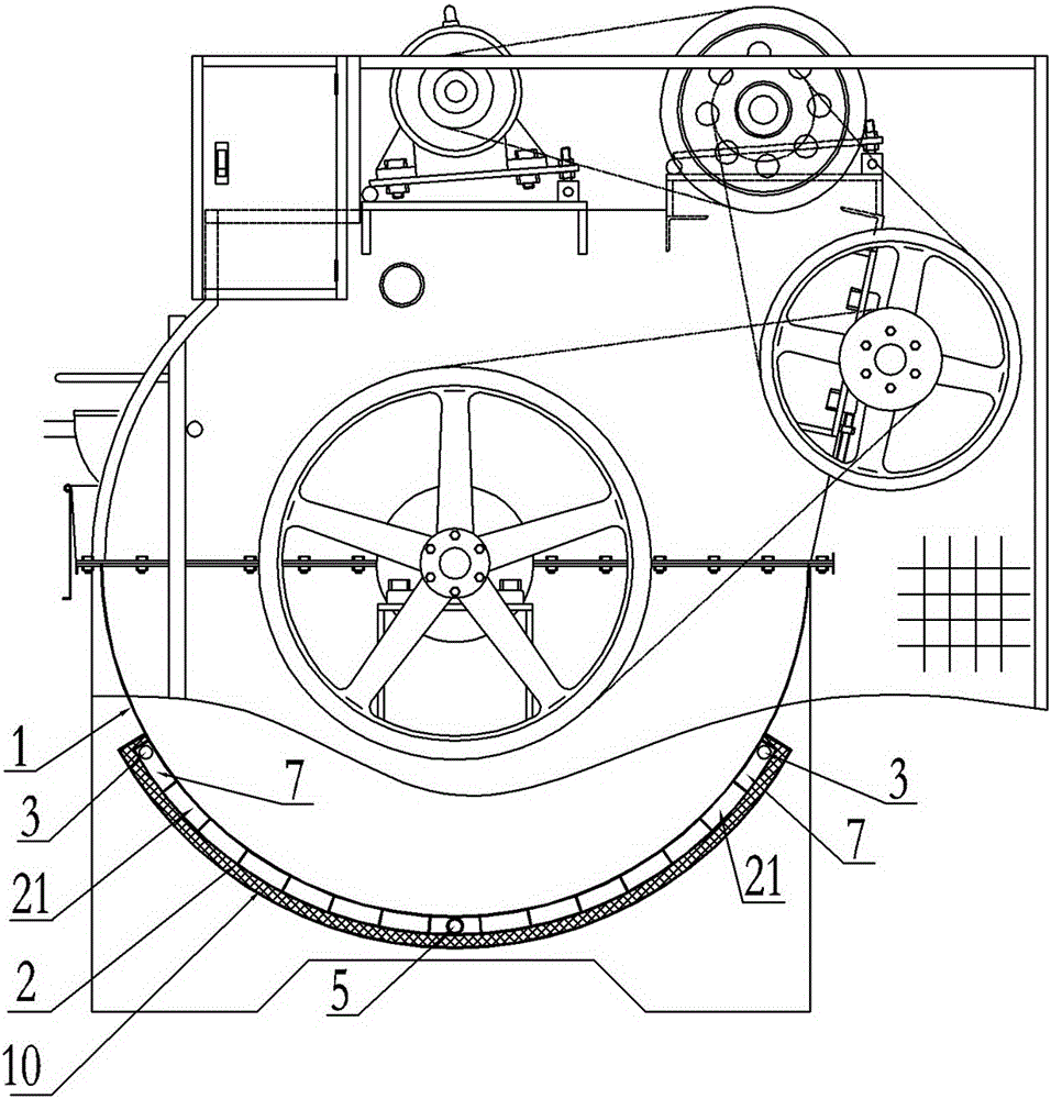
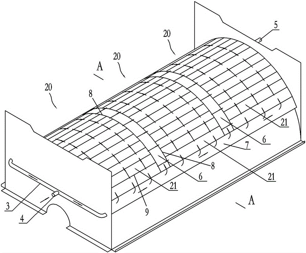
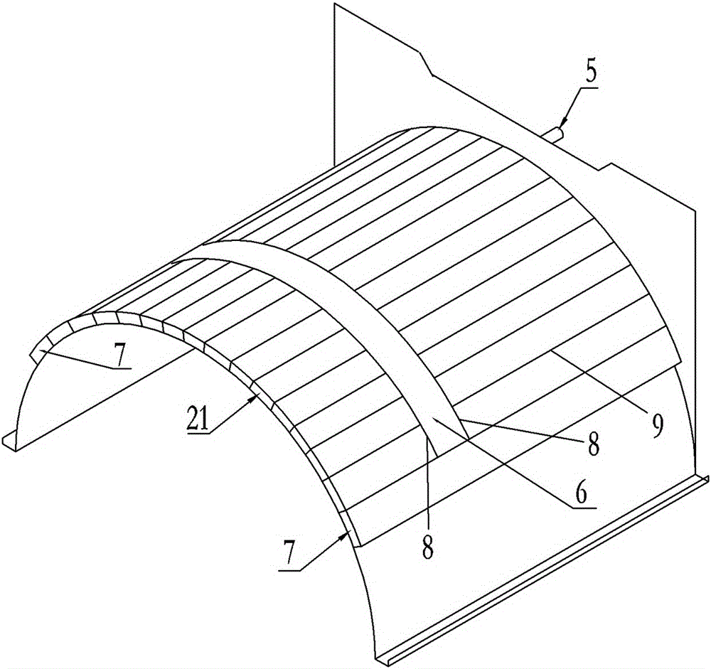
[0011] Such as Figure 1 to 3 As shown, the outside of the outer barrel 1 includes an arc-shaped heating cavity 2 wrapped at the bottom of the outer wall of the outer barrel 1. The inner space of the arc-shaped heating cavity 2 is separated by a circumferential partition 8 to form a plurality of The heating zones 20 are arranged at intervals along the axial direction, and the circumferential partitions 8 form a spacer zone 6 between the adjacent heating zones 20; the tops of both sides of each heating zone 20 are provided with air inlet channels 7 and 7 air inlet channels Are respectively connected to the top of each heating zone 20; each heating zone 20 is provided with a plurality of axial partitions 9 to divide the heating zone 20 into a plurality of axially extending sub-regions 21, and the wall surface of each adjacent sub-region 21 There are through holes connecting the adjacent sub-regions so that the steam in the adjacent sub-regions can enter the next sub-region throug...


PUM


Abstract

The invention discloses a heating device of a washing and dyeing device. The heating device is located outside an outer barrel. The inner space of an arc-shaped heating cavity of the heating device is portioned into a plurality of heating areas by partition plates in the circumferential direction, and the heating areas are arranged at intervals in the axial direction. The partition plates in the circumferential direction form interval areas between the adjacent heating areas. An air inflow channel is arranged on the tops of the two sides of each heating area and is communicated with the top of the heating area. A plurality of axial partition plates are arranged in each heating area and divide the heating area into a plurality of subareas extending in the axial direction. The wall faces of every two adjacent subareas are provided with through holes through which the adjacent subareas can be communicated. The partition plates, on the two sides of each interval area, in the circumferential direction are provided with through holes same as the subareas of the corresponding heating areas adjacent to the interval area. One end of the air inflow channel located on the tops of the two sides of the heating cavity is communicated with a steam inflow pipe through a pipeline. The bottom of the other end of the heating area located at the bottom of the heating cavity is communicated with a water outflow pipe. The heating device is long in service life, good in heating effect and capable of reducing washing and dyeing cost and improving washing and dyeing effects.

Description

Technical field [0001] The invention relates to washing and dyeing equipment, in particular to a heating device of the washing and dyeing equipment. Background technique [0002] When the washing and dyeing equipment is working, it is necessary to heat the washing liquid and / or dyeing liquid in it to keep the temperature of the washing liquid and / or dyeing liquid within an appropriate range to ensure better washing and dyeing quality. [0003] The heating device of the existing washing and dyeing equipment is generally placed at the bottom of the inner side of the outer barrel of the washing and dyeing equipment, and mainly includes a heating elbow. The steam inlet of the heating elbow is connected with the steam input pipe, and the outlet is connected with the condensate water outlet pipe. During operation, steam enters the heating elbow from the steam inlet, and exchanges heat with the washing liquid and / or dye in the outer barrel through the wall of the heated elbow in the elbo...

Claims


Application Information

Patent Timeline
Patent Type & Authority Applications(China)
IPC IPC(8): D06B23/22
Inventor 赖柏添
Owner 广州市番禺区沙湾同心机器厂
Why Eureka
Try Eureka