Electric efficient oral cavity tooth cleaner

A technology for tooth cleaners and oral cavity, applied in the field of oral cleaners, can solve the problems of easy water seepage at the connection between the punch and the handle, inconvenient and quick disassembly and assembly of the punch, breeding of bacteria, etc. Portable effect

Active Publication Date: 2021-04-16
AIR FORCE MEDICAL CENT PLA
View PDF8 Cites 1 Cited by
  • Summary
  • Abstract
  • Description
  • Claims
  • Application Information

AI Technical Summary

Problems solved by technology

[0009] The purpose of the present invention is to provide an electric high-efficiency oral tooth cleaner to solve the problems in the above-mentioned background technology that it is not convenient to quickly disassemble and assemble the punch, and the joint between the punch and the handle is easy to seep water and breed bacteria.

Method used


Image

  • Electric efficient oral cavity tooth cleaner
  • Electric efficient oral cavity tooth cleaner
  • Electric efficient oral cavity tooth cleaner

Examples


Embodiment 1

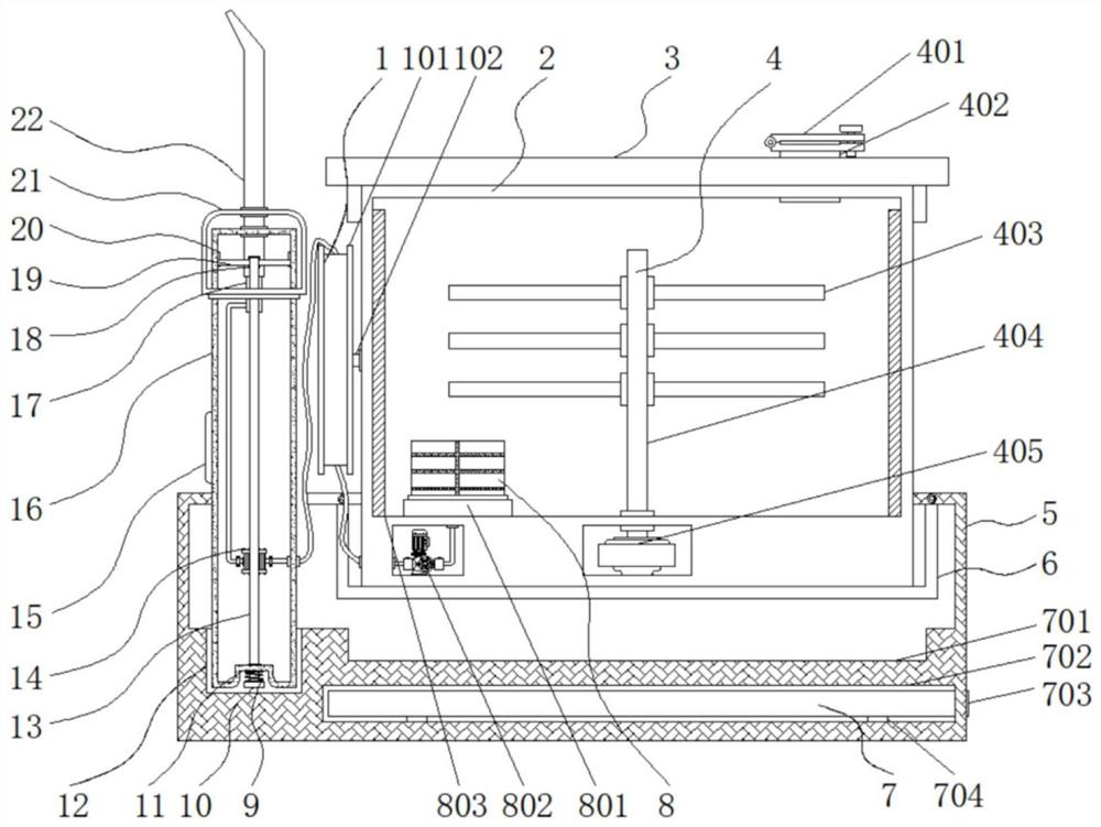
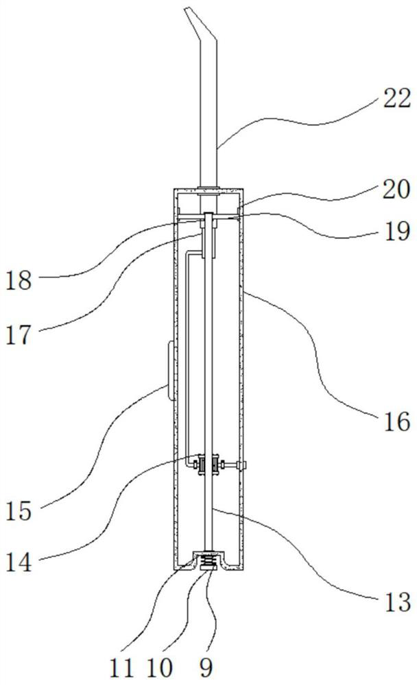
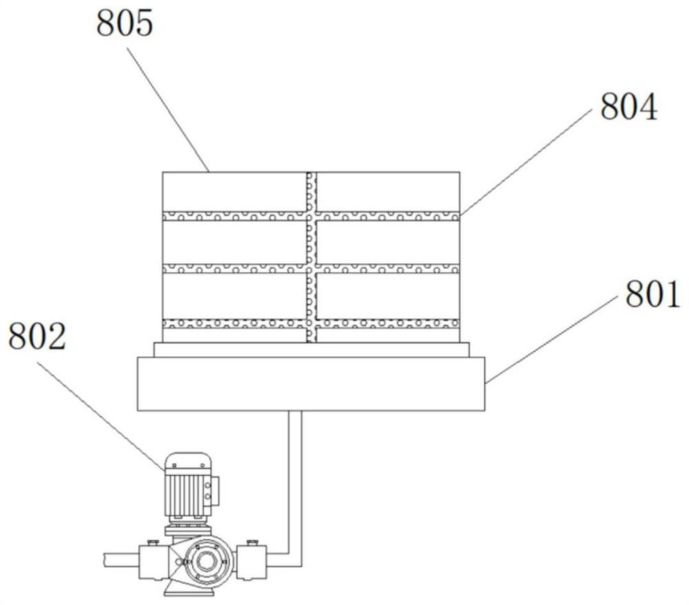
[0035] Example 1: See Figure 1-6 , an electric high-efficiency oral tooth cleaner, comprising a base 5 and a first placement slot 12, a portable storage structure 7 is provided at the bottom end inside the base 5, a first placement slot 12 is provided at one side inside the base 5, and a first placement slot 12 is provided inside the base 5 The top of the tank is provided with a tank 6, and the inside of the tank 6 is embedded with a water storage tank 2, and the top of the water storage tank 2 is fixedly connected with a tank cover 3, and one side of the water storage tank 2 is provided with a winding structure 1, and the inside of the water storage tank 2 is provided with There is a uniform liquid mechanism 4, and both sides of the inner wall of the water storage tank 2 are provided with a sterilization heating mechanism 8, and a handle 16 is embedded in the inside of the first storage tank 12, and a booster pump 14 is arranged inside the handle 16, and the booster pump 14 ...

Embodiment 2

[0039] Embodiment 2: winding structure 1 is made up of winding reel 101, movable shaft 102, first spring 103, first pressure block 104, stop bar 105, coil spring 106 and groove 107, and movable shaft 102 is movably connected in storage On one side of the water tank 2, the outside of the movable shaft 102 is movably sleeved with a winding reel 101, and the inside of the winding reel 101 is provided with a coil spring 106, and the outside of the coil spring 106 is provided with a groove 107. One end is provided with a first briquetting block 104, and a first spring 103 is fixedly connected between the bottom end of the first briquetting block 104 and the reel 101, and a stop rod 105 is arranged at the middle position of the bottom end of the first briquetting block 104, which stops The moving rod 105 vertically penetrates the inside of the winding reel 101 and is embedded in the groove 107, the inside of the coil spring 106 is wound with a hose and one end of the hose is fixedly ...

Embodiment 3

[0042] Embodiment 3: the uniform liquid mechanism 4 is made up of sealing plug 401, liquid inlet 402, stirring rod 403, rotating shaft 404 and driving motor 405, and liquid inlet 402 is arranged on the other side of box cover 3 tops, and the other side of liquid inlet 402 The bottom end communicates with the inside of the water storage tank 2, the top of the liquid inlet 402 is provided with a sealing plug 401, and the drive motor 405 is arranged inside the bottom end of the water storage tank 2. The model of the drive motor 405 can be 25GA370, and the output end of the drive motor 405 A rotating shaft 404 is fixedly connected through a coupling, and three sets of stirring rods 403 are respectively fixedly connected to both sides of the rotating shaft 404;

[0043] The rotating shaft 404 is arranged at the middle position of the bottom end of the water storage tank 2, and the stirring rods 403 are equally spaced between them;

[0044] Specifically, such as figure 1 As shown, ...


PUM


Abstract

The invention discloses an electric efficient oral cavity tooth cleaner, and particularly relates to the technical field of oral cavity cleaners, the electric efficient oral cavity tooth cleaner comprises a base and a first placement groove, a portable storage structure is arranged at the bottom end of the interior of the base, the first placement groove is formed in one side of the interior of the base, and a box groove is formed in the top end of the interior of the base. By arranging a mounting base, a suction pump, a heating layer, a composite filter screen, a filter box, a fixing frame and a heating electric wire, when the cleaner is used in winter, cold water with too low temperature brings discomfort to gingiva and teeth in the oral cavity, so that the heating layer and the heating electric wire can heat the cold water in the water storage tank, heating is stopped after the water temperature rises to 36-37 DEG C, the mouth is fully protected, irritation is reduced, meanwhile, the composite filter screen in the filter box can be used for filtering clean water to remove impurities, so that the water quality is purer, the use is more sanitary, the filter box is screwed off from the mounting base during replacement to release threaded connection, and the use experience is very comfortable.

Description

technical field [0001] The invention relates to the technical field of oral cavity cleaners, in particular to an electric high-efficiency oral cavity tooth cleaner. Background technique [0002] With the improvement of material living standards, people are paying more and more attention to oral health. Electric toothbrushes have replaced manual toothbrushes and become the most popular oral cleaning tool. However, electric toothbrushes are easy to hurt the gums and cause bleeding when cleaning the residue in the mouth, especially the gums. , so a safer water flossing tooth cleaner came into being. The tooth flossing device is also called water flossing. Water drops are used to clean the mouth. At present, dental flossers on the market can be roughly divided into portable type and seat flushing type according to volume. The portable type is small in size. The water tank is set inside the handle, and the water capacity for one-time flushing is small. The function is also relat...

Claims


Application Information

Patent Timeline
Patent Type & Authority Applications(China)
IPC IPC(8): A61C17/02
Inventor 闻静
Owner AIR FORCE MEDICAL CENT PLA
Why Eureka
Try Eureka