
Adjusting device and hydraulic machine

A technology of adjusting device and adjusting chamber, which is applied in the field of hydraulic presses, and can solve problems such as damage to the sealing contour of the valve seat of the check valve, failure of the spring seat ring, etc.

Pending Publication Date: 2021-04-16
ROBERT BOSCH GMBH
View PDF3 Cites 0 Cited by
  • Summary
  • Abstract
  • Description
  • Claims
  • Application Information

AI Technical Summary

Problems solved by technology

[0010] However, practice has shown that failures can also occur with such extended spring retainers
The reason for these faults is that under unfavorable operating conditions the spring retainer can lift off the control piston of the control valve and then return indefinitely against the control piston during decompression, so that, for example, the non-return valve The sealing profile of the valve seat is damaged
It may happen that the spring retainer is no longer moved back into the predetermined closed position on the control piston of the control valve after lifting by the force of the measuring spring, but is so tilted that the The non-return valve is permanently open—the normal function of the regulating device, in particular the superimposed pressure / delivery flow regulation, is then no longer guaranteed

Method used


Image

  • Adjusting device and hydraulic machine
  • Adjusting device and hydraulic machine
  • Adjusting device and hydraulic machine

Examples


Embodiment Construction

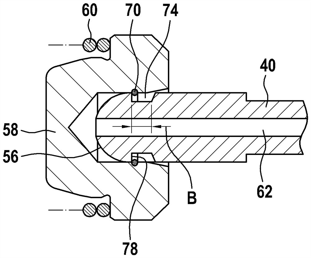
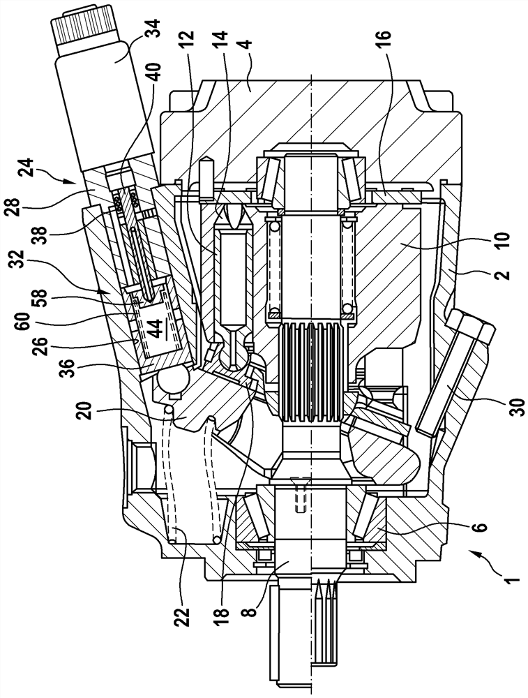
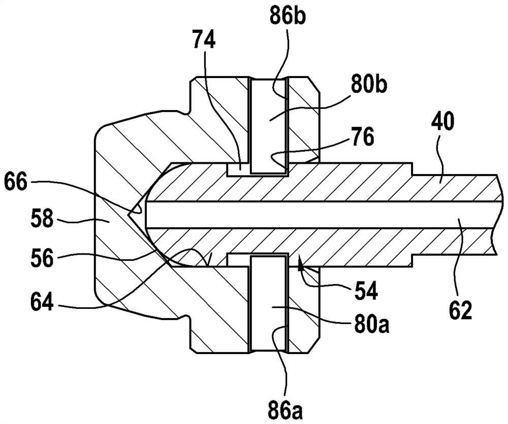
[0036] figure 1 A longitudinal section is shown of a hydraulic machine 1 embodied as an axial piston pump, which can be designed as a hydraulic pump or as a hydraulic motor. The hydraulic machine has a housing 2 and a housing cover 4 in which a shaft 8 is supported via a bearing seat 6 . The shaft is connected in a rotationally fixed manner to a cylinder 10 in which a plurality of pistons 12 is displaceably guided. Together with the cylinder 10 , these pistons each delimit a working chamber 14 , which can be connected to a high pressure or to a low pressure via a control disk 16 connected to the housing 2 , depending on the rotational position of the cylinder 10 . The bottom end section of the piston 12 facing away from the working chamber 14 is connected in each case to a slide 18 in the manner of a ball joint. These sliders 18 bear against the sliding surfaces of a swash plate 20 , also referred to as a cradle, which is rotatably supported in the housing 2 so that the pist...


PUM


Abstract

An adjusting device and a hydraulic machine provided with the adjusting device are disclosed, High control pressure can be applied to the regulating piston via a non-return valve integrated into the regulating valve. A check valve is formed by the spring seat of a measuring spring and the end section of a control piston of a regulating valve. The stroke of the spring seat ring relative to the control piston is restricted by a stroke limiting mechanism.

Description

technical field [0001] The invention relates to an adjusting device according to the preamble of claim 1 and to a hydraulic machine of axial piston construction provided with such an adjusting device. Background technique [0002] Such hydraulic machines are used, for example, as drives for fans of combustion motors. The hydraulic machine usually has a cylinder, in which a plurality of working chambers are formed, which are each delimited by an axial piston. The axial pistons are supported on the bottom side on a swash plate whose angle of rotation for adjusting the displacement can be adjusted by means of an adjusting device. In the solution known from the aforementioned prior art, the adjustment device enables a two-point adjustment for adjusting the swash plate from a minimum swivel angle to a maximum swivel angle and in the opposite direction. It is adjusted in the direction in which this adjustment takes place in steps. [0003] DE 10 2011 012 905 A1 describes a fan ...

Claims


Application Information

Patent Timeline
Patent Type & Authority Applications(China)
IPC IPC(8): F03C1/40F04B1/324
CPCF04B1/324F04B1/20F03C1/0636F03C1/0686
Inventor M·哈贝雷尔
Owner ROBERT BOSCH GMBH
Learn More