Reciprocating mechanical equipment fault detection method based on real-time vibration data

A technology for fault detection and mechanical equipment, which is used in the testing of mechanical equipment, engines, and mechanical components. It can solve problems such as strong randomness, sensitive operating conditions, and inability to locate faults. The effect of small volume and good engineering applicability

Active Publication Date: 2021-04-16
中国人民解放军92942部队
View PDF6 Cites 1 Cited by
  • Summary
  • Abstract
  • Description
  • Claims
  • Application Information

AI Technical Summary

Problems solved by technology

This method has obvious deficiencies such as poor failure, strong randomness, and incomplete testing, resulting in large errors in test results and untimely fault detection.
[0004] In addition, typical reciprocating mechanical equipment such as diesel engines and reciprocating pumps often require continuous signal monitoring and analysis. However, traditional time-domain statistical methods are sensitive to operating conditions, and can only preliminarily judge whether there is an abnormality, and cannot quickly locate faults; Theoretically, the spectrum analysis method is only suitable for constant speed and load conditions, and the Fourier spectrum does not contain time information, so it cannot be compared before and after, which is easy to cause false alarms; the time-frequency analysis method can express the joint information of time-frequency-amplitude , but involves two-dimensional matrix calculations, poor real-time performance, and the bottleneck of time-frequency resolution that cannot be optimal at the same time. There is no perfect time-frequency analysis method for engineering

Method used


Image

  • Reciprocating mechanical equipment fault detection method based on real-time vibration data
  • Reciprocating mechanical equipment fault detection method based on real-time vibration data
  • Reciprocating mechanical equipment fault detection method based on real-time vibration data

Examples


Embodiment Construction

[0023] The present invention will be described in detail below with reference to the accompanying drawings and examples.

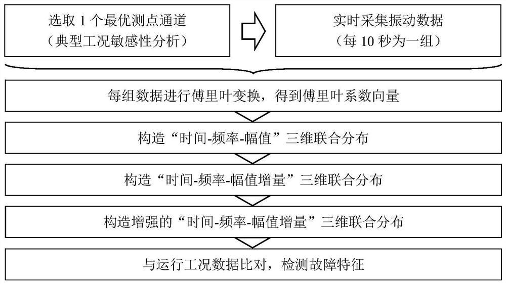
[0024] The invention provides a fault detection method for reciprocating mechanical equipment based on real-time vibration data. The specific implementation steps of the method are as follows:

[0025] Step 1: For the target equipment, set 5 load states at rated speed, which are 100% rated load, 120% rated load, 80% rated load, 50% rated load, and 20% rated load. First of all, based on experience, select common vibration measurement points such as the target equipment base, bearing seat, shell position in the reciprocating motion direction, axial position, etc., and run for 10 minutes under the above five load states to collect vibrations under each working condition. Measurement point data. Assuming that there are 10 candidate measuring points, the measured data of the nth vibration measuring point under the mth working condition is written as x mn , wh...


PUM


Abstract

The invention discloses a reciprocating mechanical equipment fault detection method based on vibration data, and relates to the technical field of diesel engine operation state monitoring. The method comprises the following steps: firstly, aiming at target equipment, optimizing a measuring point channel which is most sensitive to an operation state through working condition sensitivity analysis; in the actual operation process of the target equipment, collecting a vibration signal of the optimal measuring point channel in real time; performing Fourier transform on each new data segment to obtain a Fourier coefficient vector; continuously arranging the Fourier coefficient vectors of different data segments in the time direction to obtain 'time-frequency-amplitude' three-dimensional joint distribution of the vibration data of the channel, and constructing 'time-frequency-amplitude increment' three-dimensional joint distribution and enhanced 'time-frequency-amplitude increment' three-dimensional joint distribution; and finally, comparing with operation condition data, and detecting fault characteristics. According to the invention, information extraction can be effectively carried out on reciprocating mechanical equipment in real time, and faults can be found and positioned in time.

Description

technical field [0001] The invention relates to the technical field of diesel engine operation state monitoring, in particular to a method for detecting faults of reciprocating mechanical equipment based on vibration data. Background technique [0002] Typical reciprocating mechanical equipment such as diesel engines and reciprocating pumps have the characteristics of complex structure, precise mechanism, and high-speed movement. Reciprocating mechanical equipment is usually used as a power source or driver and is an important equipment in the system. However, in actual engineering, reciprocating mechanical equipment often has poor installation environment, long continuous working hours, high reliability requirements, and difficult repairs. Fault detection is essential for reciprocating mechanical equipment. Good detection methods can effectively avoid major faults and cause serious economic losses. Generally speaking, the requirements for fault detection in engineering are...

Claims


Application Information

Patent Timeline
Patent Type & Authority Applications(China)
IPC IPC(8): G01H17/00G01M15/02G01M15/12G01M13/00
CPCY02T10/40
Inventor 刘隆波张衍冯志鹏陈小旺贺喆畅晓鹏王新鹏刘鹏鹏许友林
Owner 中国人民解放军92942部队
Why Eureka
Try Eureka