

Wire foil winding mechanism method for three-dimensional iron core
A wire foil coil, iron core technology, applied in coil manufacturing, inductance/transformer/magnet manufacturing, electrical components, etc. Specifications, improve winding efficiency, improve the effect of winding quality
- Summary
- Abstract
- Description
- Claims
- Application Information
AI Technical Summary
Problems solved by technology
Method used
Image

Examples
no. 1 approach
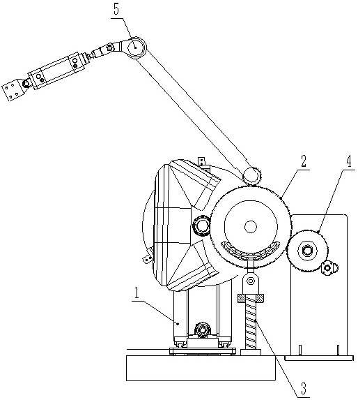
[0077] This embodiment relates to a wire foil winding mechanism for a three-dimensional iron core, refer to figure 1 , including at least a core clamping device 1 for adjusting the angle of the target three-dimensional iron core, a driven winding device 2 and a driving gear device 4 sleeved on the target stem, wherein the driving gear device 4 meshes to drive the driven winding device The device 2 rotates around the target stem, and the driven winding device 2 drives the wire foil to wind on the target stem during the rotation.
[0078] The working process of the wire foil winding mechanism for the three-dimensional iron core is as follows:
[0079] Take the three-dimensional iron core to be wound with the wire foil as the target three-dimensional iron core, hoist the target three-dimensional iron core on the iron core clamping device 1 and clamp and position it, so that the driven winding device 2 is sleeved on the target core of the target three-dimensional iron core Column...
no. 2 approach
[0086] This embodiment relates to a wire foil winding mechanism for a three-dimensional iron core, refer to figure 1 , including at least a core clamping device 1 for adjusting the angle of the target three-dimensional iron core, a driven winding device 2 sleeved on the target stem, and a driving gear device 4, wherein the driving gear device 4 meshes to drive the driven winding device The winding device 2 rotates around the target stem, and the driven winding device 2 drives the wire foil to wind on the target stem during the rotation.
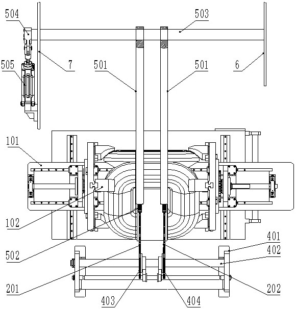
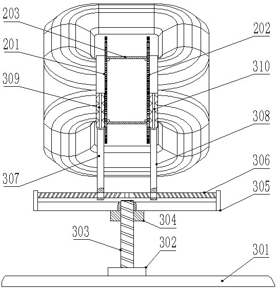
[0087] refer to image 3 , the driven winding device 2 includes two driven gears sleeved in parallel and opposite to the target stem, which are respectively the first driven gear 201 and the second driven gear 202, and the opposite of the two driven gears The end faces are provided with an annular boss with the same diameter and coaxial, and a hollow cylindrical bush 203 made of insulating material is sleeved on the annular boss, and the tar...
no. 3 approach
[0118] This embodiment provides a wire foil winding method for a three-dimensional iron core. The winding method includes:
[0119] The three-dimensional iron core to be wound with wire foil is used as the target three-dimensional iron core;
[0120] Lift the target three-dimensional iron core to the iron core clamping device 1 and clamp and position it;
[0121] Set the driven winding device 2 on the target stem of the target three-dimensional iron core;
[0122] Fix the high and low voltage line foil on the driven winding device 2;
[0123] The driving gear device 4 meshes to drive the driven winding device 2 to rotate around the target stem;
[0124] During the rotation process, the driven winding device 2 drives the wire foil to wind on the target stem.
[0125] The above-mentioned winding method is mainly used in the wire foil winding mechanism, which at least includes a core clamping device 1 for adjusting the angle of the target three-dimensional iron core, a driven ...
PUM
 Abstract
Description
Claims
Application Information