Microgrid power droop control device and control method thereof

A technology of power droop and control device, applied in the direction of reducing/preventing power oscillation, single-network parallel feeding arrangement, etc., can solve the problems of temperature rise of transmission line, affecting the output power of droop controller, and easy to increase line resistance, etc. To achieve the effect of preventing the increase of resistance value, reducing the temperature, and preventing the influence

Inactive Publication Date: 2021-04-16
GUANGDONG POLYTECHNIC COLLEGE
View PDF7 Cites 0 Cited by
  • Summary
  • Abstract
  • Description
  • Claims
  • Application Information

AI Technical Summary

Problems solved by technology

[0003] During the working process of the droop controller, multiple power inverters need to be connected in the circuit. Since the resistance of the transmission line increases with the increase of temperature, once the circuit load is heavy, the temperature of the transmission line will rise. High, and then it is easy to increase the line resistance, which is easy to affect the output power of the droop controller

Method used


Image

  • Microgrid power droop control device and control method thereof
  • Microgrid power droop control device and control method thereof
  • Microgrid power droop control device and control method thereof

Examples


Embodiment Construction

[0031]The implementation mode of the present invention is illustrated by specific specific examples below, and those who are familiar with this technology can easily understand other advantages and effects of the present invention from the contents disclosed in this description. Obviously, the described embodiments are a part of the present invention. , but not all examples. Based on the embodiments of the present invention, all other embodiments obtained by persons of ordinary skill in the art without making creative efforts belong to the protection scope of the present invention.

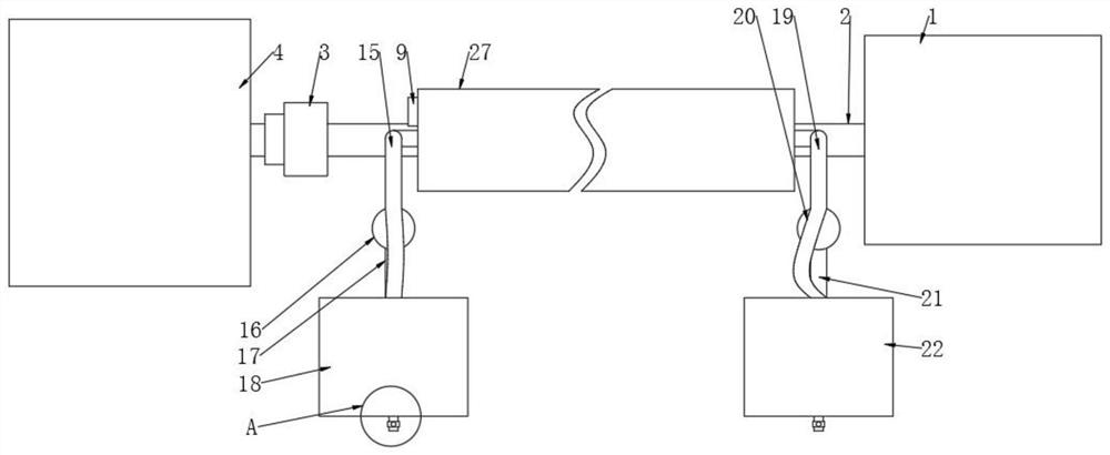
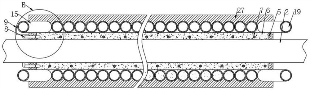
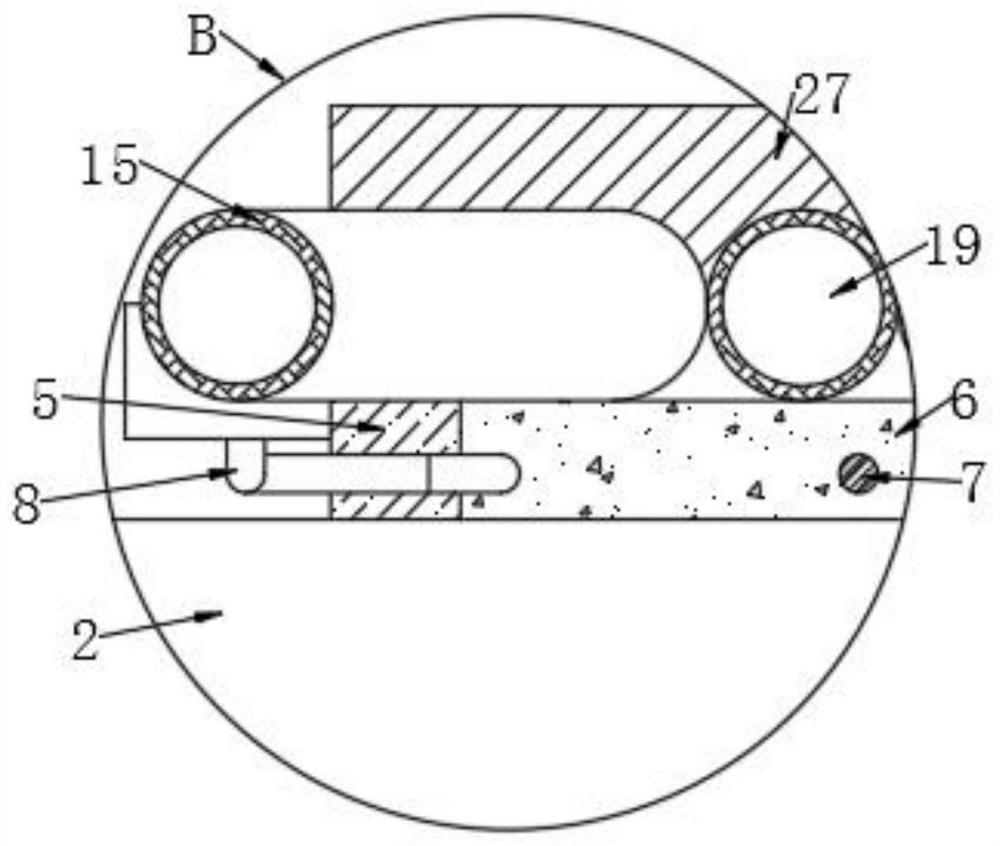
[0032] Refer to the attached Figure 1-7 , a microgrid power droop control device according to this embodiment, comprising a droop controller main body 1, a control mechanism and a cooling mechanism are provided on one side of the droop controller main body 1, and the cooling mechanism is arranged outside the control mechanism;

[0033] The control mechanism includes a heat-conducting silica gel ...


PUM


Abstract

The invention discloses a microgrid power droop control device and a control method thereof, and particularly relates to the technical field of droop control equipment. The microgrid power droop control device comprises a droop controller main body, one side of the droop controller main body is provided with a control mechanism and a cooling mechanism, and the cooling mechanism is arranged outside the control mechanism; the control mechanism comprises heat conduction silica gel, the heat conduction silica gel is fixedly arranged at the outer end of the first wire, a thermistor wire is arranged in the heat conduction silica gel and fixedly connected with the heat conduction silica gel, the two ends of the thermistor wire penetrate through the heat conduction silica gel and extend out of one side of the heat conduction silica gel, and a storage battery is fixedly arranged at one end of the second wire. According to the droop controller, the temperature of the first wire is detected by using the thermistor wire, and when the temperature is relatively high, cold water can be automatically introduced into the first heat dissipation pipe and the second heat dissipation pipe, so that the first wire can be cooled, the resistance of the first wire is prevented from being increased, and the influence on the output power of the droop controller main body can be avoided.

Description

technical field [0001] Embodiments of the present invention relate to the technical field of droop control equipment, and in particular to a microgrid power droop control device and a control method thereof. Background technique [0002] With the continuous increase of electricity load in recent years, the construction of power grid has not developed synchronously with the increase of load, which has led to the continuous expansion of long-distance transmission capacity, and the operation stability and safety of the power grid system. sexual descent. In view of the above problems, after continuous development and improvement, distributed power generation technology came into being. The so-called distributed generation refers to the establishment of a separate micro-power source in the distribution network to supply power to the loads in the distribution network, and connect to the large power grid through a public connection point, and can exchange energy with the external ...

Claims


Application Information

Patent Timeline
IPC IPC(8): H02J3/38H02J3/24
Inventor 胡林林付龙关健李欣雪龙小丽
Owner GUANGDONG POLYTECHNIC COLLEGE
Why Eureka
Try Eureka